1-5
Cisco Network Convergence System 6000 Series Routers Site Planning Guide
OL-29236-02
Chapter 1 Cisco NCS 6008 Chassis
Chassis Slot Numbers
Chassis Slot Numbers
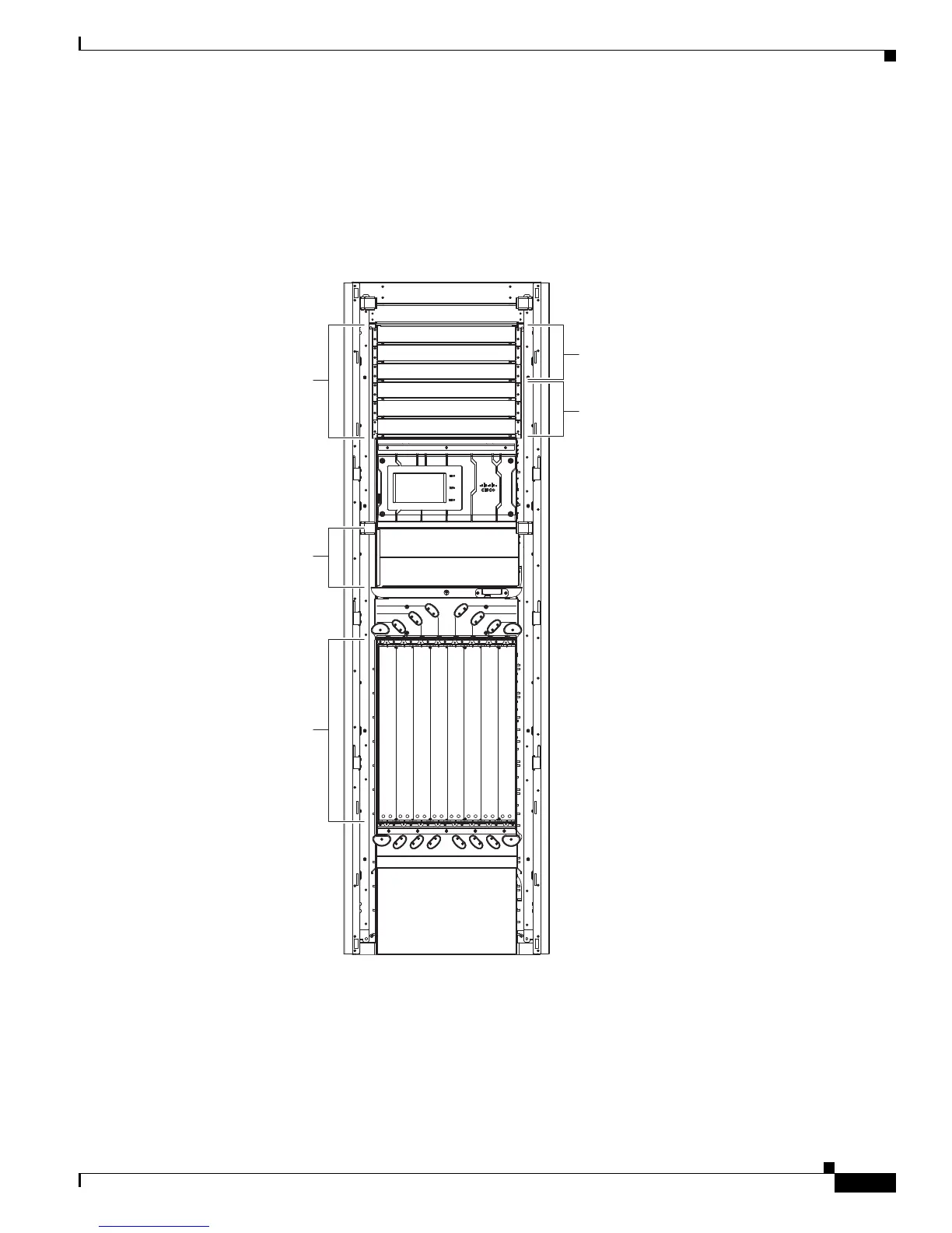
This section identifies the location and slot numbers for system components that plug into the chassis.
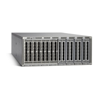
Figure 1-3 shows the slot numbers on the front (LC) side of the chassis.
Figure 1-3 Cisco NCS 6008 Chassis Slot Numbers—Front Side
As shown, the front (LC) side of the chassis has the following card slots:
• Eight LC slots (left to right: 0, 1, 2, 3, 4, 5, 6, 7).
• Two fan trays for redundancy. The fan trays are accessed from the front side of the chassis.
• Six power trays for redundancy.
The upper three AC power trays (0-2) are contained within power shelf 0 (PS0) and the lower three AC
power trays (3-5) are contained within power shelf 1 (PS1).
361588
PT0
PT1
PT2
PT3
PT5
FT0
FT1
PT4
Slot 0
Slot 1
Slot 2
Slot 3
Slot 4
Slot 5
Slot 6
Slot 7
LC0
LC1
LC2
LC3
LC4
LC5
LC6
LC7
Power trays
Upper power shelf (PS0)
Lower power shelf (PS1)
Line cards
Fan trays
 Loading...