5-11
Cisco Wide Area Virtualization Engine 7541, 7571, and 8541 Hardware Installation Guide
Chapter 5 WAVE Interface Modules
Installation Scenarios and Cabling Examples for Fast Ethernet Connections
Two WAVE appliances with inline network adapters can also be installed back-to-back in a serial fashion
between two network devices for failover purposes. In this serial cluster configuration, if one WAVE
appliance fails, the other WAVE appliance can provide optimization. (See Figure 5-11.)
Note When you connect two WAVE inline appliances to each other serially, always use a crossover cable
between the two WAVE appliances. (See Figure 5-12.)
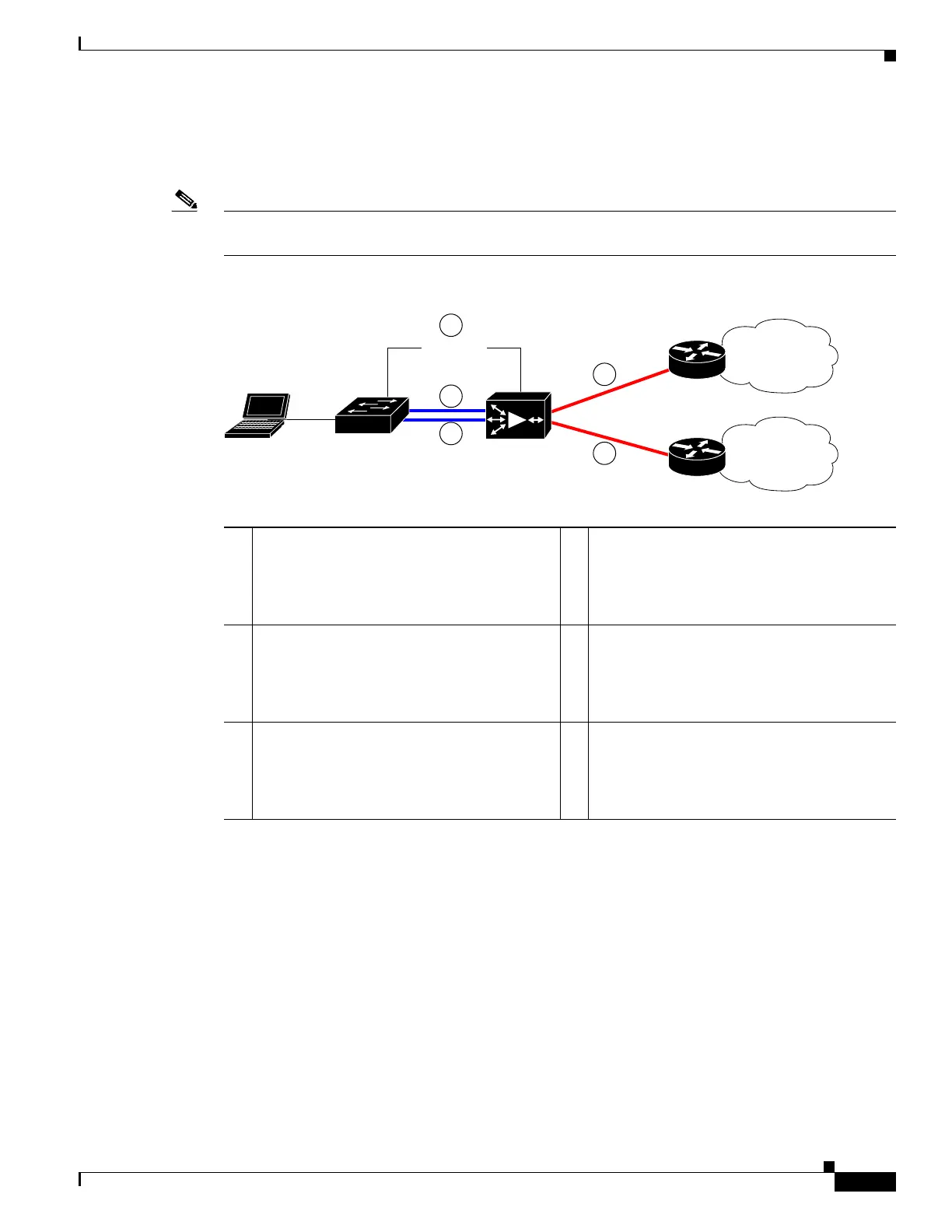
Figure 5-10 Cabling for a Single Inline WAVE Appliance with Redundant WAN Connections
1 Connection: Management
Gigabit Ethernet: 1/0
Cable type: Straight-through (recommended)
2 Connection: WAVE to LAN switch
(using InlineGroup 1/0)
Fast Ethernet: LAN0 (InlinePort 1/0/lan)
Cable type: Straight-through
3 Connection: WAVE to LAN switch
(using InlineGroup 1/1)
Fast Ethernet: LAN1 (InlinePort 1/1/lan)
Cable type: Straight-through
4 Connection: WAVE to WAN router A
(using InlineGroup 1/0)
Fast Ethernet: WAN0 (InlinePort 1/0/wan)
Cable type: Crossover
5 Connection: WAVE to WAN router B
(using InlineGroup 1/1)
Fast Ethernet: WAN1 (InlinePort 1/1/wan)
Cable type: Crossover
MGMT
243288
WAVE
WAN
WAN
Router A
Router B
LAN switch
1
4
5
2
3