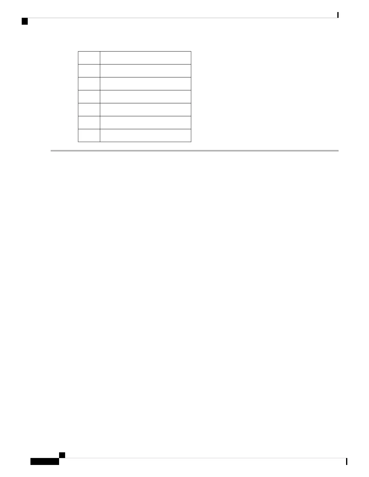
Part DescriptionQuantity
M4 x 6-mm Phillips flat-head screws18
M4 x 6-mm Phillips pan-head screws2
Rack-mount guides2
Rack-mount guide rails2
Grounding cover plate1
Grounding lug1
Step 1 Install the rack-mount brackets to the router as follows:
a) Determine which end of the chassis is to be located in the cold aisle as follows:
• If the router has port-side intake modules (fan modules and power modules with burgundy coloring), position
the router so that the ports are in the cold aisle.
• If the router has port-side exhaust modules (fan modules and power modules with blue coloring), position the
router so that the fan and power supply modules are in the cold aisle.
b) Position a rack-mount bracket on the side of the chassis with its four holes that are aligned to four of the screw holes
on the side of the chassis, and then use four M4 flat-head screws with 23 in-lbs (2.6 N-m) torque value to attach the
bracket to the chassis.
(Only 8201) Remove the grounding cover label and align the grounding cover plate with the grounding
holes in the chassis and attach the rack mount brackets.
Note
You can align four holes in the rack-mount bracket to four screw holes on the front side of chassis or four
screw holes on the rear side of the chassis. The holes that you use depend on which end of your chassis is
located in the cold aisle.
Note
Hardware Installation Guide for Cisco 8200 Series Routers
14
Installing the Chassis
Rack-Mount the Chassis in a 4-Post Rack
 Loading...