1-13
Cisco Video Surveillance 8620/8630 IP Camera Reference Guide
Chapter 1 Getting Started
Hardware Installation
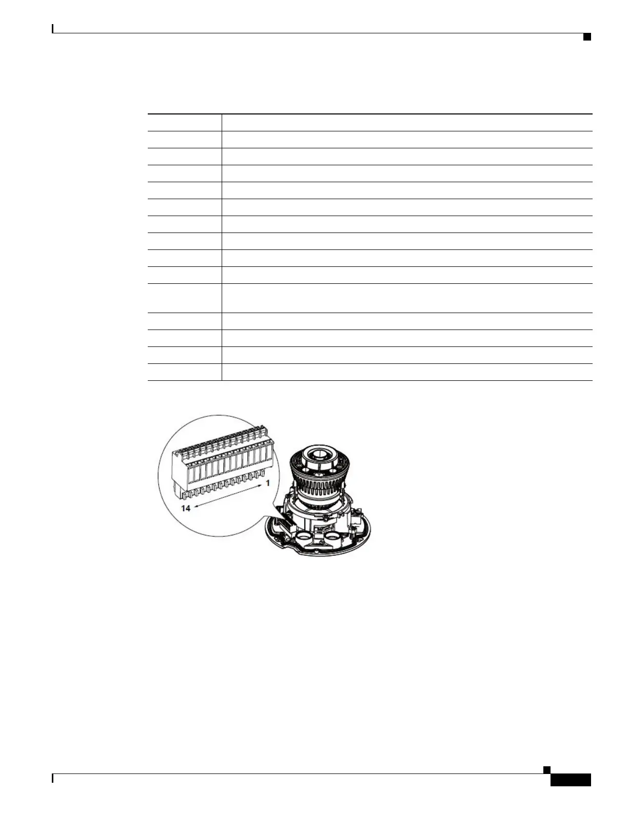
Step 8 The following table and figure show the pinouts. The DI/DO, audio, and power wires are user-supplied.
#Name
1AC 24V
2AC 24V
3DC 12V IN–
4DC 12V IN+
5 VIDEO-OUT N
6 VIDEO-OUT P
7 DI- (Common GND for all DI, DO, MIC-IN, and AUDIOOUT)
8DI+ 1
9DI+ 0
10 DO– 1 (If external devices are powered by external sources, can use DI– as common
ground)
11 DO– 0
12 DO+ (5V; if used, can be paired with DO– 0 and DO– 1.)
13 MIC-IN P
14 AUDIO-OUT P