1-18
Cisco Video Surveillance 8620/8630 IP Camera Reference Guide
Chapter 1 Getting Started
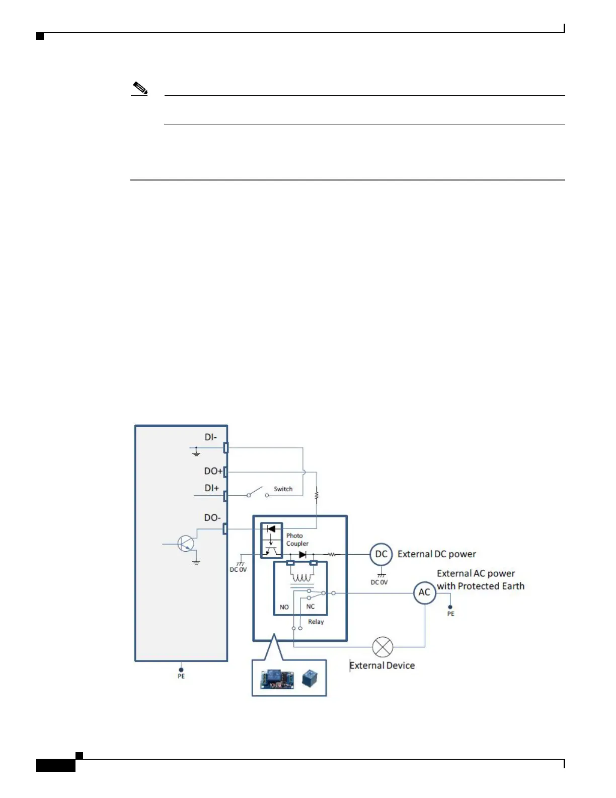
DI/DO Diagram
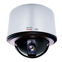
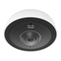
Note Do not loosen the other 6 anti-tamper screws on the top of the dome cover. They are used to hold
the dome cover components in place.
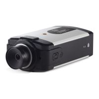
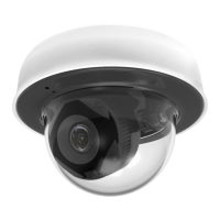
Step 16 Access the camera web-based user interface and choose Configuration > Media > Image > Focus page.
You will see a live stream on screen. If preferred, you can zoom in on the scene. Use the Perform Auto
Focus function to automatically tune to a best image focus.
DI/DO Diagram
• The DO+ pin provides a 5V output, and the max. load is 50mA.
• The max. voltage for DO- pins is 30VDC (External power).
In order to control AC devices, the following diagram can be taken into consideration. This diagram
uses a relay to control the ON/OFF condition of the AC device.
• An external relay can be triggered by using the DO+ or by an external power source, depending on
the type of relay you use.
• In case of using an individual relay (instead of using a relay module), for protection against voltage
or current spikes, a transient voltage suppression diode must be connected in parallel with the
inductive load.
The following figure shows dry contact with external DC power source to supply a relay. Dry contact is
the safest connection to protect devices.