Module ReceptacleConnector
TX/RX40 G Interface_LaneReceptacle FiberFiber IDConnector ID
——10F10MPO10
——11F11MPO11
——12F12MPO12
——13F13MPO13
TX0_014F14MPO14
TX0_115F15MPO15
TX0_216F16MPO16
TX0_317F17MPO17
TX1_018F18MPO18
TX1_119F19MPO19
TX1_220F20MPO20
TX1_321F21MPO21
——22F22MPO22
——23F23MPO23
——24F24MPO24
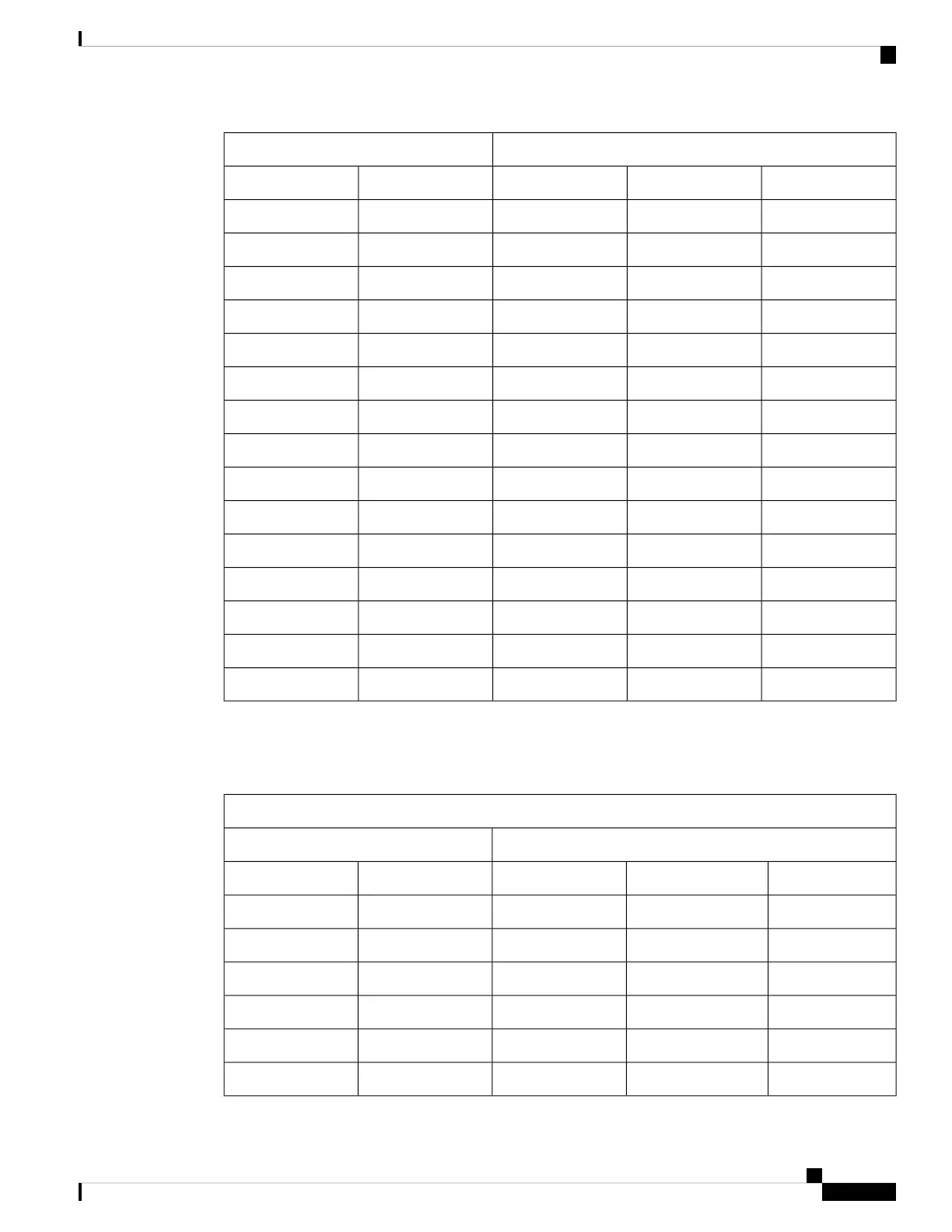
The following table shows the pinouts for 40G interface 0 and 40G interface 1. For both interfaces, pins 5, 6,
7, and 8 are not used.
Table 33: 100G to 2X40G Y-Cable Pinouts (40G Side)
40 G Interface 0
Module Receptacle
Connector
TX/RX40 G Interface_LaneReceptacle Fiber
Fiber IDConnector ID
RX0_01F14MPO1
RX0_12F15MPO2
RX0_23F16MPO3
RX0_34F17MPO4
——5F13MPO5
——6F23MPO6
Cisco ASR 9000 Series Aggregation Services Router Ethernet Line Card Installation Guide
155
Technical Specifications
Technical Specifications