MeaningStateColorLED Label
SPA power is on and good, and SPA is being configured.OnAmber
SPA is ready and operational.OnGreen
Port is not enabled by software.OffOffA/C
Port is enabled by software.OnGreen
Port is enabled by software, and there is at least one alarm.OnAmber
24-Port Channelized T1/E1/J1 CEoP SPA Interface Specifications
The physical layer interface for the 24-Port Channelized T1/E1/J1 CEoP SPA is a customer-installed
high-density connector. This connector has thumbscrews that should be screwed into the SPA when the cable
is installed.
24-Port Channelized T1/E1/J1 CEoP SPA Cables and Connectors
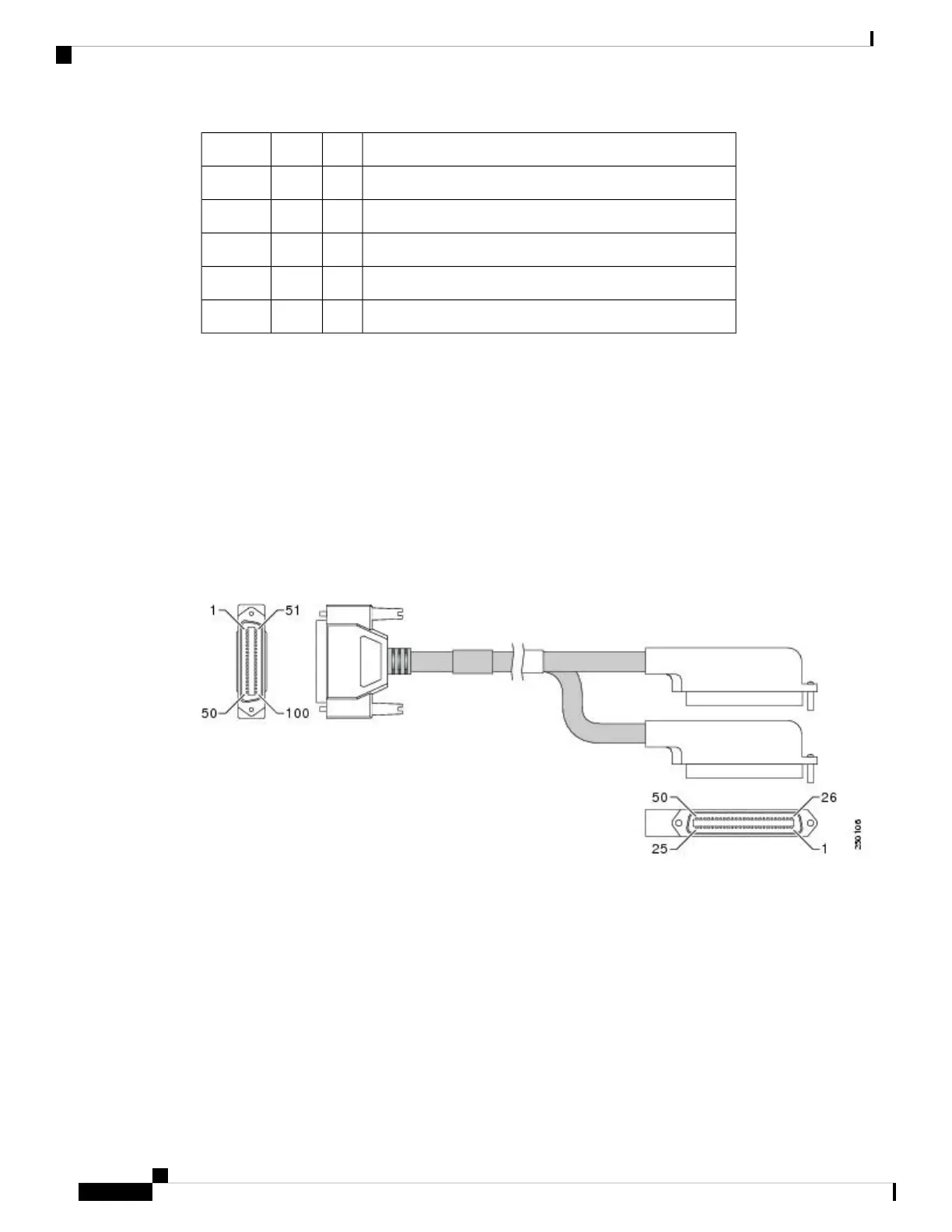
The 24-Port Channelized T1/E1/J1 CEoP SPA requires a Cisco cable (part number CABLE-24T1E1J1), which
is shown in the figure below.
Figure 52: 24-Port Channelized T1/E1/J1 CEoP SPA High-Density Cable
Cable Installation
One end of the cable has a 100-pin connector that plugs into the front of the 24-Port Channelized T1/E1/J1
CEoP SPA. Use the thumbscrews on either side of the connector to secure the cable to the SPA.
The other end of the cable has two 50-pin Telco connectors that can be attached to the rear of a 24-port RJ-45
patch panel. Both connectors are identical: one is for Transmit (TX) and the other is for Receive (RX). The
following figure shows how the cable is connected between the 24-Port Channelized T1/E1/J1 CEoP SPA
and the patch panel.
Cisco ASR 9000 Series Aggregation Services Router SIP and SPA Hardware Installation Guide
62
Overview: Cisco ASR 9000 Series Router Shared Port Adapters
24-Port Channelized T1/E1/J1 CEoP SPA Interface Specifications
 Loading...


