1-4
Cisco Aironet 1300 Series Outdoor Access Point/Bridge Hardware Installation Guide
OL-5048-02
Chapter 1 Overview
Key Features
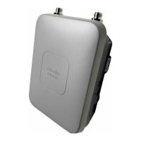
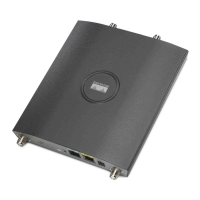
External Antenna
The access point/bridge is available in an external antenna configuration (see Figure 1-1) for use with
Cisco Aironet 2.4-GHz antennas. Two reverse-TNC type RF connectors are provided on the end of the
unit to support single or diversity antenna configurations.
The antennas connect to the access point/bridge antenna connectors using a coax cable. These are some
of the external antennas supported by the access point/bridge:
• 5.2-dBi omnidirectional antenna with vertical polarization
• 12-dBi omnidirectional antenna with vertical polarization
• 9-dBi patch wall mount antenna
• 10-dBi yagi antenna
• 13.5-dBi yagi antenna
• 14-dBi sector antenna with vertical polarization
• 21-dBi dish antenna
Note To meet regulatory restrictions, the external antenna access point/bridge unit and the external antenna
must be professionally installed. The network administrator or other IT professional responsible for
installing and configuring the unit is a suitable professional installer. Following installation, access to the
unit should be password protected by the network administrator to maintain regulatory compliance.
Ethernet Ports
The access point/bridge dual-coax Ethernet ports consists of a pair of 75-ohm F-type connectors, linking
the unit to your 100BASE-T Ethernet LAN through the power injector. The dual-coax cables are used to
send and receive Ethernet data and to supply inline 48-VDC power from the power injector to the access
point/bridge. For the location of the ports, refer to Figure 1-3.
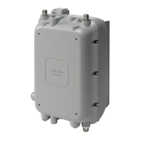
Enclosure
The access point/bridge uses an enclosure that supports indoor or outdoor operating environments. (refer
to “Access Point/Bridge Specifications” section on page C-1).
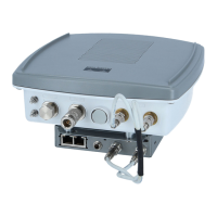
Connectors
The connectors (see Figure 1-2) provided depend upon the access point/bridge configuration:
• Integrated antenna access point/bridge configuration
–
Dual-coax Ethernet connectors—used to provide Ethernet signals and in-line power
• External antenna access point/bridge configuration
–
Dual-coax Ethernet connectors—used to provide Ethernet signals and in-line power
–
Dual antenna connectors—used to support a single antenna or dual-diversity antennas
 Loading...