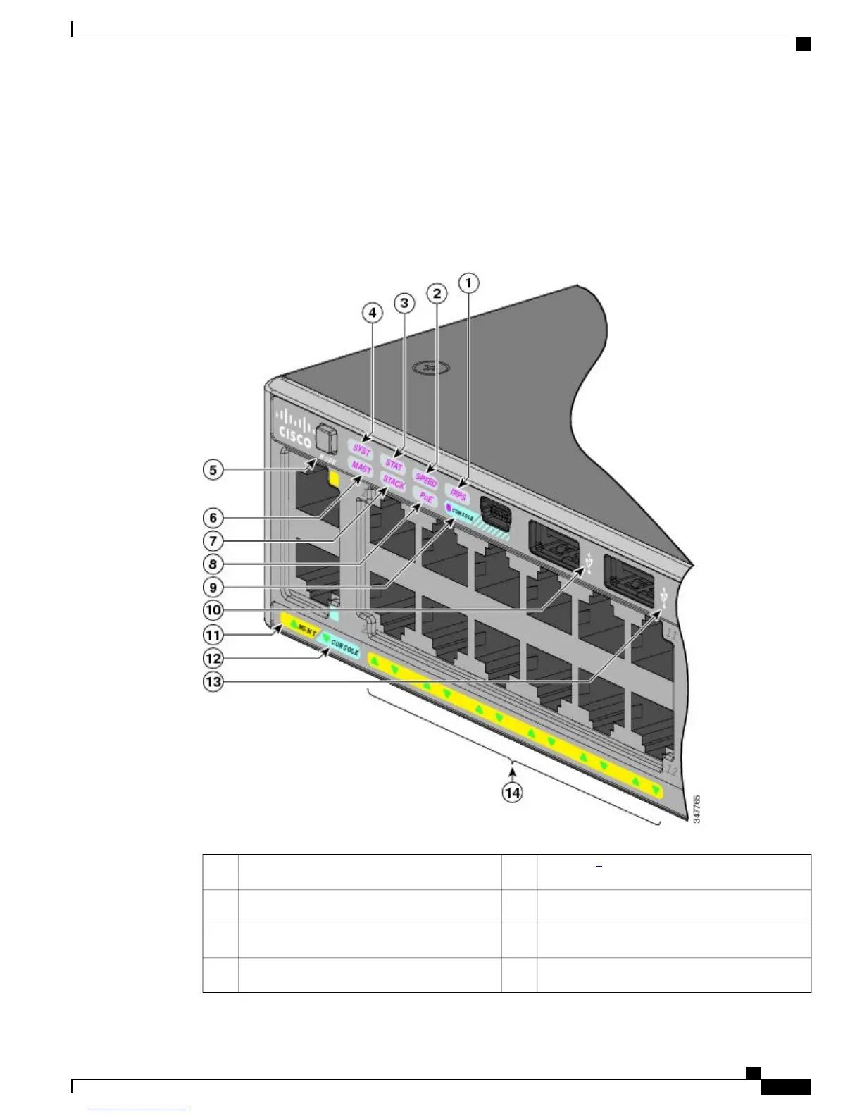
EasyManuals Logo

Cisco Catalyst 250 Series Hardware Installation Guide

Cisco Catalyst 250 Series
102 pages
To Next Page IconTo Next Page
To Previous Page IconTo Previous Page
Page #19 background imageLoading...
Page #19 background image
4
RPS = redundant power systemonly on switch models that support RPS.
5
Only on switch models that support PoE.
6
Only on switch models that support stacking.
This figure shows the switch LEDs and the Mode button that you use to select a port mode.
Figure 5: Switch LEDs and Mode Button for the Catalyst 2960-XR Switch
PoE LED
7
8IRPS LED1
USB mini-Type B console port LED9SPEED LED2
USB Type A port10STAT LED3
MGMT LED11SYS LED4
Catalyst 2960-X and 2960-XR Switch Hardware Installation Guide
OL-28309-02 9
Product Overview
LEDs

Table of Contents

Other manuals for Cisco Catalyst 250 Series

Questions and Answers:

Question and Answer IconNeed help?

Do you have a question about the Cisco Catalyst 250 Series and is the answer not in the manual?

Cisco Catalyst 250 Series Specifications

General IconGeneral
BrandCisco
ModelCatalyst 250 Series
CategorySwitch
LanguageEnglish

Related product manuals