PS OK LED4FlexStack-Plus module slot and cover1
AC power connector on the power supply module5Power supply slot (with blank module)2
AC OK LED3
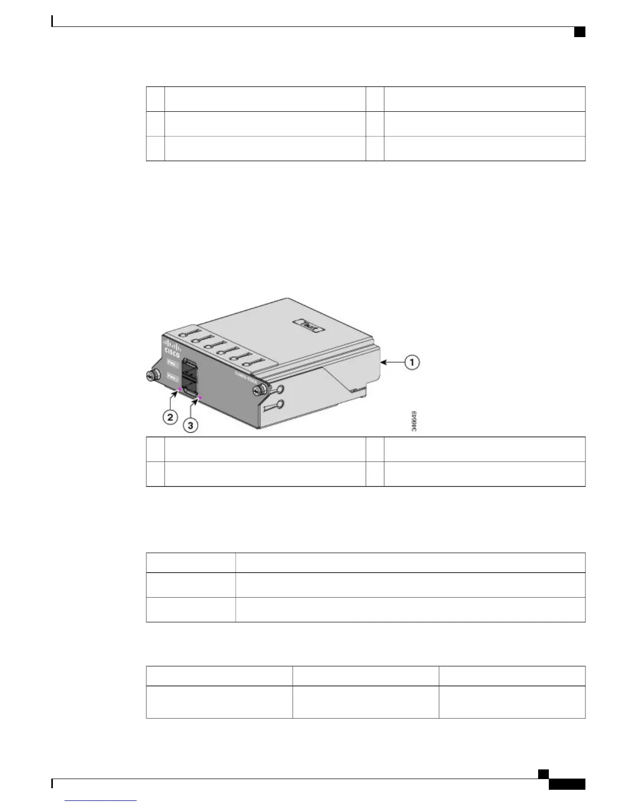
FlexStack-Plus Ports and LEDs
The stacking-capable switch models support stacking with the optional stack kit. It has the FlexStack-Plus
module (hot-swappable) that inserts in the slot located in the switch rear panel, and a 0.5-meter FlexStack
cable to connect the FlexStack-Plus module ports.
Figure 9: FlexStack-Plus Module
LED for Stack port 23FlexStack-Plus module1
LED for Stack port 12
This table lists the FlexStack-Plus module LED colors and their meanings.
Table 11: FlexStack-Plus Module LEDs
DescriptionColor
Port is active, cable is attached.Green
The port is not active, no cable is attached.Off
Table 12: Stack Configurations
BandwidthNumber of Switches in the StackSwitch
80 G8Stack with Catalyst 2960-X
stack-capable switches
Catalyst 2960-X and 2960-XR Switch Hardware Installation Guide
OL-28309-02 17
Product Overview
FlexStack-Plus Ports and LEDs
 Loading...