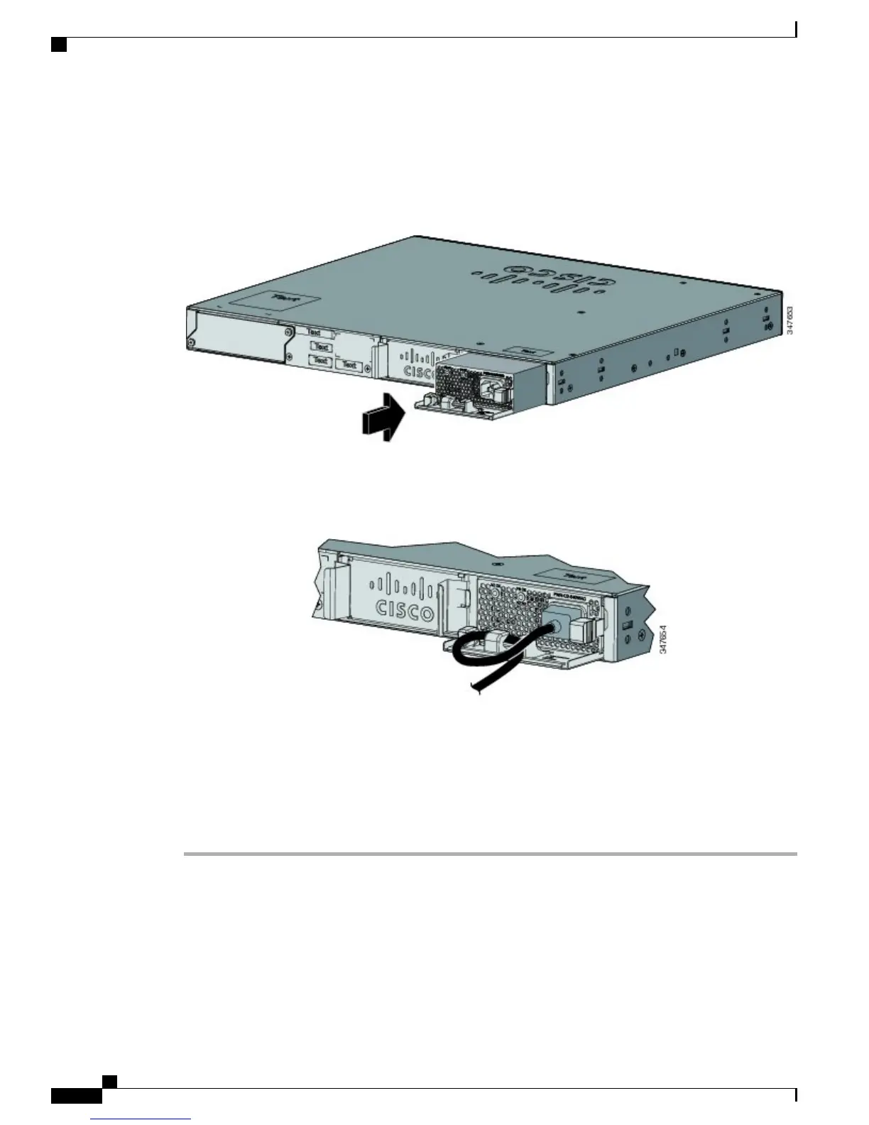
Step 5
Insert the new power supply into the power-supply slot, and gently push it into the slot. When correctly
inserted, the 250-W and 640-W power supplies (excluding the power cord retainer) are flush with the switch
rear panel. The 1025-W power-supply module extends inches from the switch rear panel.
Figure 34: Inserting the AC-Power Supply in the Switch
Step 6
(Optional) Make a loop in the power cord and thread it through the power cord retainer.
Figure 35: AC-Power Supply with Power Cord Retainer
Step 7
Connect the power cord to the power supply and to an AC power outlet. Turn on the power at the power
source.
Step 8
Confirm that the power supply AC OK and PS OK LEDs are green.
Step 9
Repeat the steps to install a second power supply.
When you install the second power supply the LEDs on the power supply might blink momentarily.Note
Catalyst 2960-X and 2960-XR Switch Hardware Installation Guide
58 OL-28309-02
Power Supply Installation
Installing or Replacing an AC Power Supply
 Loading...