B-7
Catalyst 3550 Multilayer Switch Hardware Installation Guide
78-11358-03
Appendix B Connector and Cable Specifications
Cable and Adapter Specifications
You can order a kit (part number ACS-DSBUASYN=) containing that adapter
from Cisco. For console port and adapter pinout information, see Table B-2 and
Table B-3.
Cable and Adapter Specifications
These sections describe the cables and adapters used with Catalyst 3550 switches.
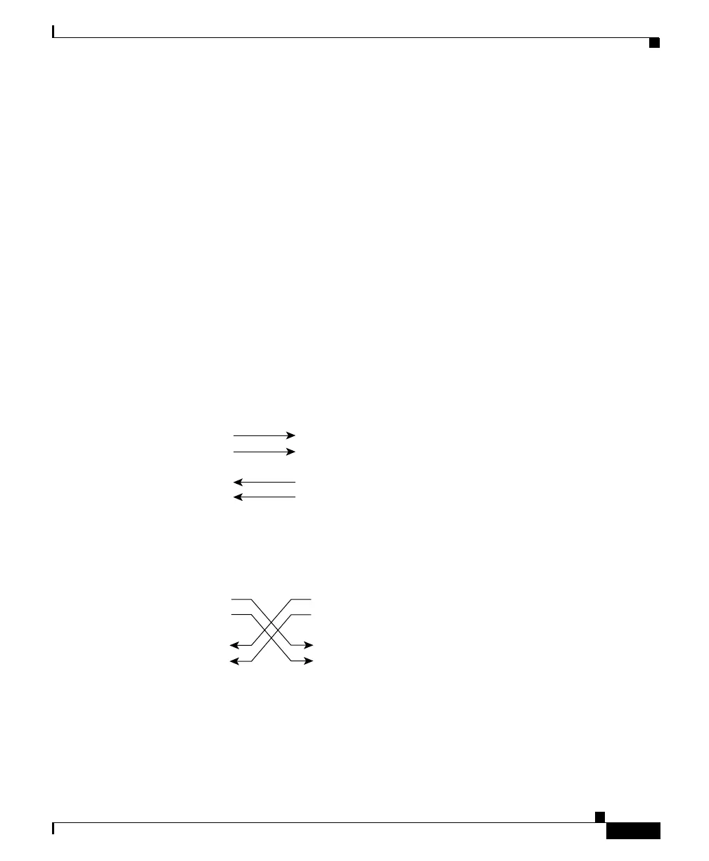
Two Twisted-Pair Cable Pinouts
Figure B-7 and Figure B-8 show the schematics of two twisted-pair cables for
10/100 ports.
Figure B-7 Two Twisted-Pair Straight-Through Cable Schematic
Figure B-8 Two Twisted-Pair Crossover Cable Schematic
Four Twisted-Pair Cable Pinouts for 10/100 Ports
Figure B-9 and Figure B-10 show the schematics of four twisted-pair cables for
10/100 ports.
Switch
3 TD+
6 TD–
1 RD+
2 RD–
Switch
3 RD+
6 RD–
1 TD+
2 TD–
H5578
Switch
3 TD+
6 TD–
1 RD+
2 RD–
Switch
3 TD+
6 TD–
1 RD+
2 RD–
H5579