2-17
Catalyst 3550 Multilayer Switch Hardware Installation Guide
78-11358-03
Chapter 2 Installing and Starting the Switch
Installing the Switch
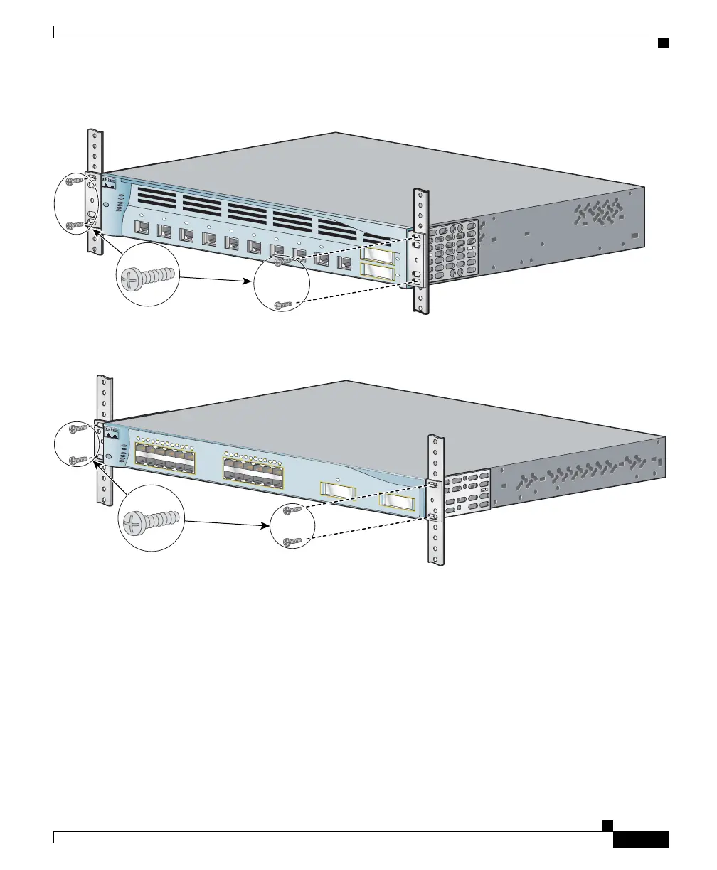
Figure 2-13 Mounting the Catalyst 3550-12T and 3550-12G Switches in a Rack
Figure 2-14 Mounting the Catalyst 3550-24, 3550-48, 3550-24-FX, and 3550-24-DC Switches in a Rack
After the switch is mounted in the rack, see the “Attaching the Cable Guide”
section on page 2-17 and the “Powering On the Switch” section on page 2-24 to
complete the installation.
Attaching the Cable Guide
We recommend attaching the cable guide to prevent the cables from obscuring the
front panel of the switch and the other devices installed in the rack. Use the
supplied black screw, as shown in Figure 2-15 and Figure 2-16 to attach the cable
guide to the left or right bracket.
MODE
SY
STEM
RPS
STA
TUS
UTIL
DUPLX
SPEED
2
1
1
2
3
4
5
6
7
8
9
10
Catalyst 3550
SERIES
74033
Phillips machine screws
M
O
D
E
S
Y
S
T
E
M
1X
2X
15X
16X
R
P
S
S
T
A
T
U
S
U
T
IL
D
U
P
L
X
S
P
E
E
D
1
2
3
4
5
6
7
8
9
10
11
12
1
1X
2X
15X
16X
1
2
3
4
5
6
7
8
9
10
11
12
2
Catalyst 3550
SERIES
74021
Phillips machine screws