2-13
Catalyst 3550 Multilayer Switch Hardware Installation Guide
78-11358-03
Chapter 2 Installing and Starting the Switch
Installing the Switch
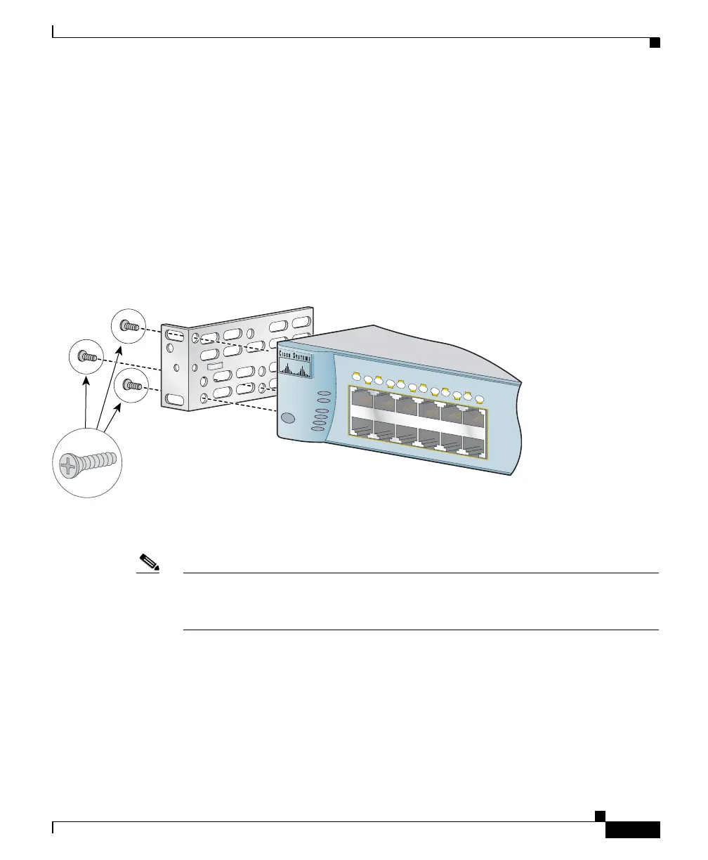
Attaching Brackets to the Catalyst 3550-24 and 3550-48, 3550-24-FX, and
3550-24-DC Switches
The bracket orientation and the brackets you use depend on whether you are
attaching the brackets for a 19-inch or a 24-inch rack. For 19-inch racks, use
bracket part number 700-8209-01; for 24-inch racks, use bracket part number
700-13248-01. Figure 2-7 through Figure 2-12 show how to attach each type
bracket to one side of the switch. Follow the same steps to attach the second
bracket to the opposite side.
Figure 2-7 Attaching Brackets for 19- and 24-Inch Racks, Front Panel Forward
Note Before you attach the brackets on the Catalyst 3550-24-FX switch, remove the
screws that are on the bottom-front of the chassis. Attach the bracket by using the
supplied Phillips flat-head screws, as shown in Figure 2-7.
MODE
SYSTEM
1
X
2
X
1
1X
12
X
RPS
S TAT U S
UTIL
DUPLX
SPEED
1
2
3
4
5
6
7
8
9
10
11
12
Phillips
flat-head
screws
19" Configuration
60138