Chapter 1 Product Overview
Front-Panel Description
1-6
Catalyst 3550 Multilayer Switch Hardware Installation Guide
78-11358-03
The Catalyst 3550-24, 3550-48, and 3550-24-DC 10/100 ports are grouped in
pairs. The first member of the pair (port 1) is above the second member (port 2)
on the far left, as shown in Figure 1-9 and Figure 1-10. Port 3 is above port 4, and
so on. The GBIC port numbers are 1 (left) and 2 (right).
The Catalyst 3550-24-FX 100BASE-FX ports are numbered 1 through 24 (port 1
is on the far left , as shown in Figure 1-11) and the GBIC port numbers are 1 (top)
and 2 (bottom).
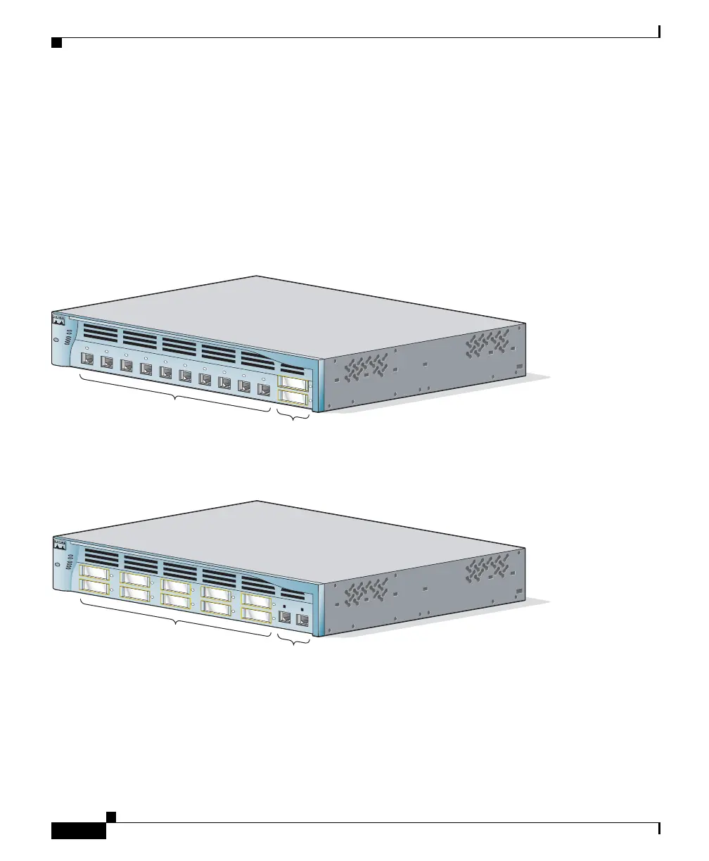
Figure 1-2 Catalyst 3550-12T Front Panel
Figure 1-3 Catalyst 3550-12G Front Panel
M
O
D
E
S
Y
S
T
E
M
R
P
S
S
T
A
T
U
S
U
T
IL
D
U
P
LX
S
P
E
E
D
1
2
1
1
1
2
3
4
5
6
7
8
9
1
0
Catalyst 3550
SERIES
10/100/1000
ports
GBIC
module slots
74025
MODE
SYSTEM
RPS
STATUS
UTIL
DUPLX
SPEED
2
1
4
3
6
5
8
7
1
0
9
1
1
1
2
Catalyst 3550
SERIES
10/100/1000
ports
GBIC
module slots
74038