Chapter 1 Product Overview
Rear-Panel Description
1-22
Catalyst 3550 Multilayer Switch Hardware Installation Guide
78-11358-03
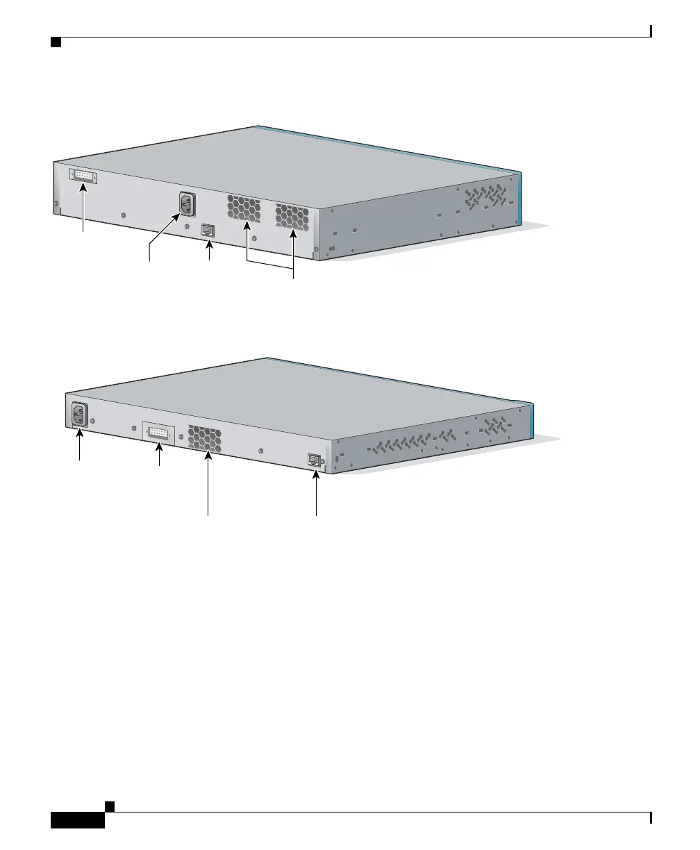
Figure 1-17 Catalyst 3550-12T and 3550-12G Rear Panel
Figure 1-18 Catalyst 3550-24, 3550-48, and 3550-24-FX Rear Panel
The rear panel of the 3550-DC has a DC power connector (also referred to as the
terminal block header), an RJ-45 console port, and a ground lug. (See
Figure 1-19.) The switch is shipped with a terminal block plug inserted into the
DC power connector.
100-240V~
5-3A
50/60Hz
DC OUTPUT 1
CO
NS
OLE
50374
AC power
connector
Redundant
power
system
connector
Fan
exhaust
RJ-45
console
port
100-240V~
5-3A
50/60Hz
DC OUTPUT 1
C
ON
SO
LE
AC power
connector
Redundant
power
system
connector
Fan
exhaust
RJ-45
console
port
49803