EasyManuals Logo

Cisco Catalyst 4500 Series Overview

Cisco Catalyst 4500 Series
46 pages
To Next Page IconTo Next Page
To Previous Page IconTo Previous Page
Page #44 background imageLoading...
Page #44 background image
Chapter 1 Module Overview and Specifications
Switching Module LEDs
1-44
Catalyst 4500 Series Module Installation Guide
78-13267-06
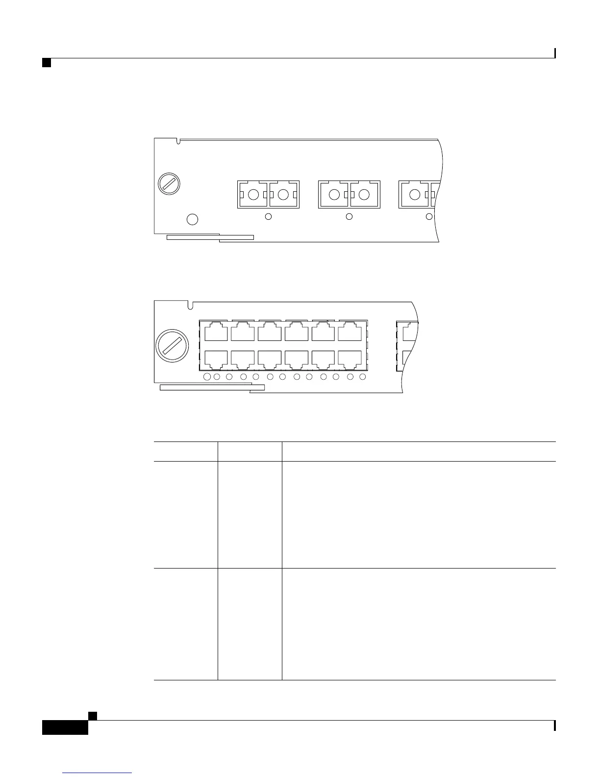
Figure 1-40 Gigabit Ethernet Port and Status LEDs
Figure 1-41 10/100BASE-T Port LEDs
1
26854
1000BASE-X SWITCHING MODULE
STATUS
2 3
WS-X4306-GB GIGABIT ETHERNET
17407
STATUS
4
1
2
3
4
5
5
6
6
7
7
8
8
9
9
10
10
11
12
11
12
WS-X4148-RJ
4 PORT
10/100 B
Table 1-3 Switching Module LEDs
LED Color/State Description
STATUS Indicates the results of a series of self-tests and
diagnostic tests performed by the switch.
Green All the tests pass.
Red A test other than an individual port test failed.
Orange System boot, self-test diagnostics running, or the
module is disabled.
LINK
1
Indicates the status of the 10BASE-T port.
Green The port is operational (a signal is detected).
Orange The link has been disabled by software.
Flashing
orange
The link has been disabled due to a hardware failure.
Off No signal is detected.

Other manuals for Cisco Catalyst 4500 Series

Questions and Answers:

Question and Answer IconNeed help?

Do you have a question about the Cisco Catalyst 4500 Series and is the answer not in the manual?

Cisco Catalyst 4500 Series Specifications

General IconGeneral
SeriesCatalyst 4500 Series
CategorySwitch
Layer SupportLayer 2, Layer 3
Form FactorModular chassis
StackableNo
Chassis Slots3, 6, 7, 10
Power Supply OptionsAC, DC
RedundancyPower supply, Supervisor engine
Network ManagementCisco IOS Software CLI, SNMP, Cisco Prime Infrastructure
FeaturesSecurity, QoS
Port DensityUp to 384 ports per chassis
Security Features802.1X, ACLs, DHCP Snooping, Dynamic ARP Inspection, IP Source Guard
Supervisor Engine8-E

Related product manuals