EasyManuals Logo

Cisco Catalyst 4500 Series Overview

Cisco Catalyst 4500 Series
46 pages
To Next Page IconTo Next Page
To Previous Page IconTo Previous Page
Page #43 background imageLoading...
Page #43 background image
1-43
Catalyst 4500 Series Module Installation Guide
78-13267-06
Chapter 1 Module Overview and Specifications
Switching Module LEDs
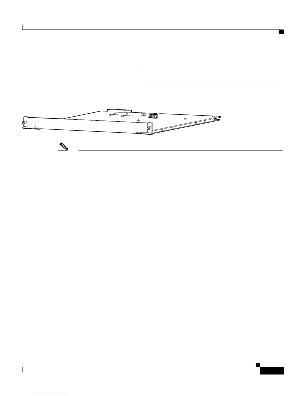
Figure 1-39 WS-X4019 Backplane Channel Module
Note The backplane channel module is supported by only the WS-X4013 supervisor
engine in the Catalyst 4006, 4503, or 4506 switches using the Catalyst Operating
System.
Access Gateway Module (WS-X4604-GWY)
The Access Gateway Module is described in the Catalyst 4000 Access Gateway
Module Installation and Configuration Note (DOC-7810818).
Switching Module LEDs
Each switching module has one LED labeled STATUS that provides information
about the module and one numbered LED labeled LINK for each port on the
module. Figure 1-40 shows the Gigabit Ethernet port and status LEDs.
Figure 1-41 shows the 10/100BASE-T port LEDs. Table 1-3 describes the
switching module LEDs.
Connector type
Cable type
Specification Description
38301
STATUS

Other manuals for Cisco Catalyst 4500 Series

Questions and Answers:

Question and Answer IconNeed help?

Do you have a question about the Cisco Catalyst 4500 Series and is the answer not in the manual?

Cisco Catalyst 4500 Series Specifications

General IconGeneral
SeriesCatalyst 4500 Series
CategorySwitch
Layer SupportLayer 2, Layer 3
Form FactorModular chassis
StackableNo
Chassis Slots3, 6, 7, 10
Power Supply OptionsAC, DC
RedundancyPower supply, Supervisor engine
Network ManagementCisco IOS Software CLI, SNMP, Cisco Prime Infrastructure
FeaturesSecurity, QoS
Port DensityUp to 384 ports per chassis
Security Features802.1X, ACLs, DHCP Snooping, Dynamic ARP Inspection, IP Source Guard
Supervisor Engine8-E

Related product manuals