EasyManuals Logo

Cisco Catalyst 9124AX Series User Manual

Cisco Catalyst 9124AX Series
118 pages
To Next Page IconTo Next Page
To Previous Page IconTo Previous Page
Page #78 background imageLoading...
Page #78 background image
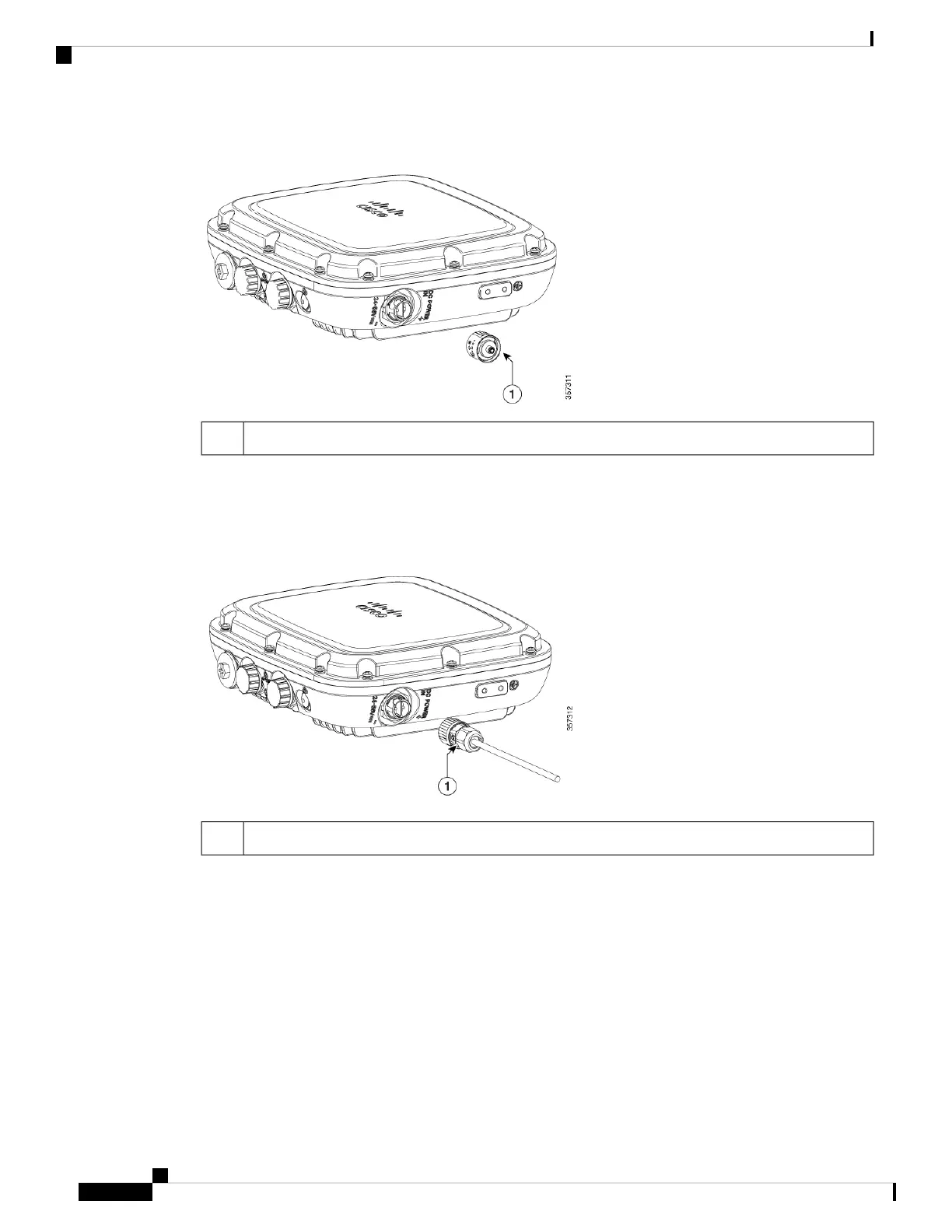
Figure 76: Position of the DC Power-In Port on the Right Side of the AP
DC Connector Cap1
Step 4 Insert DC supply 2-pin connector into plug located on the left side of the AP. Position and orient the plug to
align with the keyed pins on the connector. Push inward toward the AP until the connector body rotates and
clicks into place. The plug is a bayonet-style. It should automatically lock into place when pushed inward.
Figure 77: Installing the DC plug
2-Pin DC plug1
Step 5 If the AP is to be power with customer supplied DC source. The following steps show how to terminate the
Cisco-supplied DC plug to the cable.
Cisco Catalyst 9124AX Series Outdoor Access Point Hardware Installation Guide
70
Installation Overview
Connecting a DC Power Cable to the Access Point

Table of Contents

Questions and Answers:

Question and Answer IconNeed help?

Do you have a question about the Cisco Catalyst 9124AX Series and is the answer not in the manual?

Cisco Catalyst 9124AX Series Specifications

General IconGeneral
Wi-Fi StandardWi-Fi 6 (802.11ax)
Frequency Bands2.4 GHz, 5 GHz
MIMO4x4
IP RatingIP67
Spatial Streams4
Power Options802.3at PoE+, DC power adapter
RadiosDual Radio (2.4 GHz and 5 GHz)
AntennaInternal
Power over EthernetYes
MountingWall, ceiling, pole
Weight1.2 kg
SecurityWPA3, WPA2, WPA
ManagementCisco DNA Center, CLI, WebUI
Ethernet Ports1 x 10/100/1000/2500 Multigigabit Ethernet (RJ-45)
Dimensions220 x 220 x 66 mm

Related product manuals