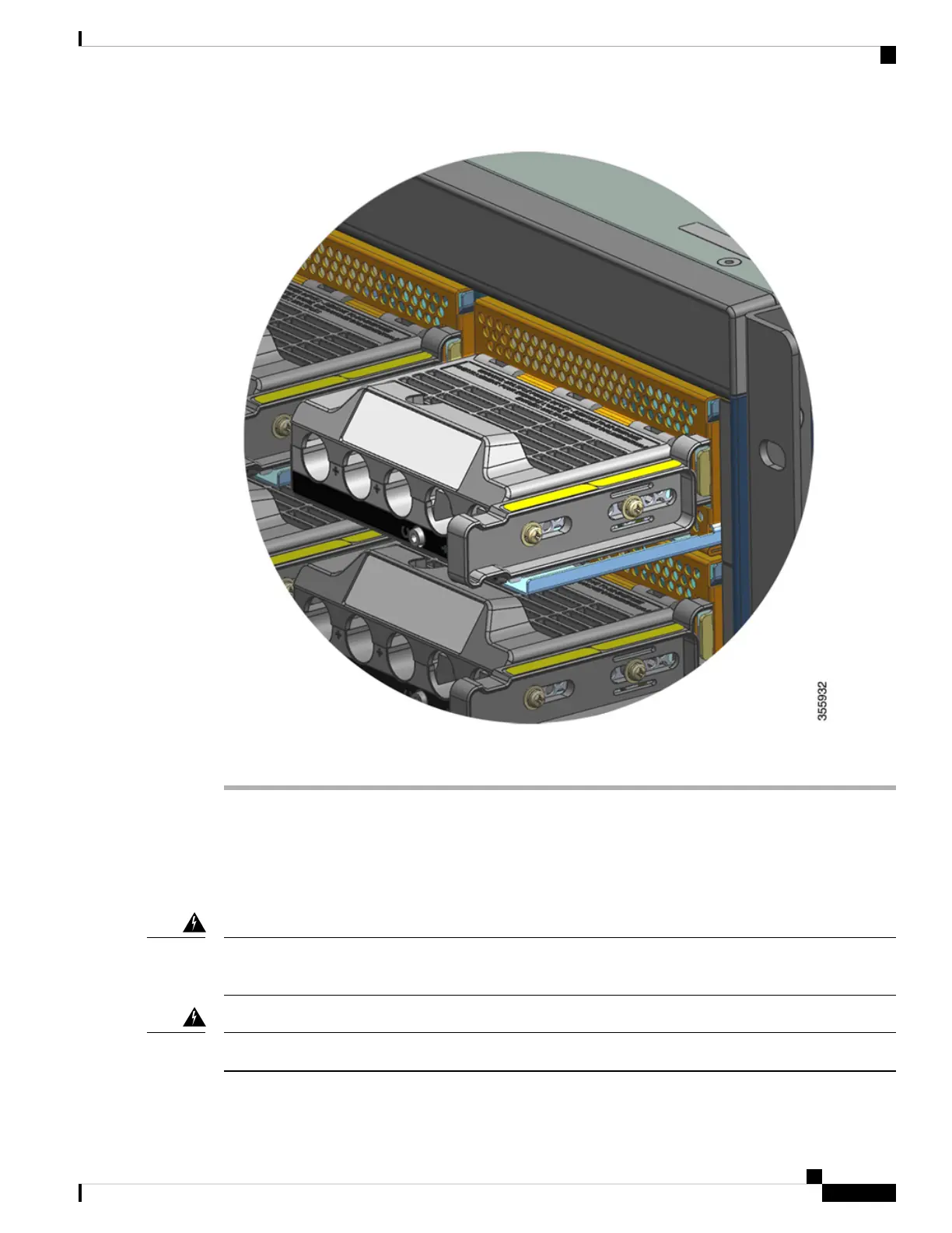
Connecting the DC-Input Wires
To connect to the DC-input power source, follow the steps described here.
Before you begin
Only trained and qualified personnel should be allowed to install, replace, or service this equipment. Statement
1030
Warning
No user-serviceable parts inside. Do not open. Statement 1073
Warning
Cisco Catalyst 9400 Series Switches Hardware Installation Guide
119
Removing and Replacing FRUs
Connecting the DC-Input Wires

 Loading...


