EasyManuals Logo

Cisco Catalyst 9400 Series User Manual

Cisco Catalyst 9400 Series
192 pages
To Next Page IconTo Next Page
To Previous Page IconTo Previous Page
Page #58 background imageLoading...
Page #58 background image
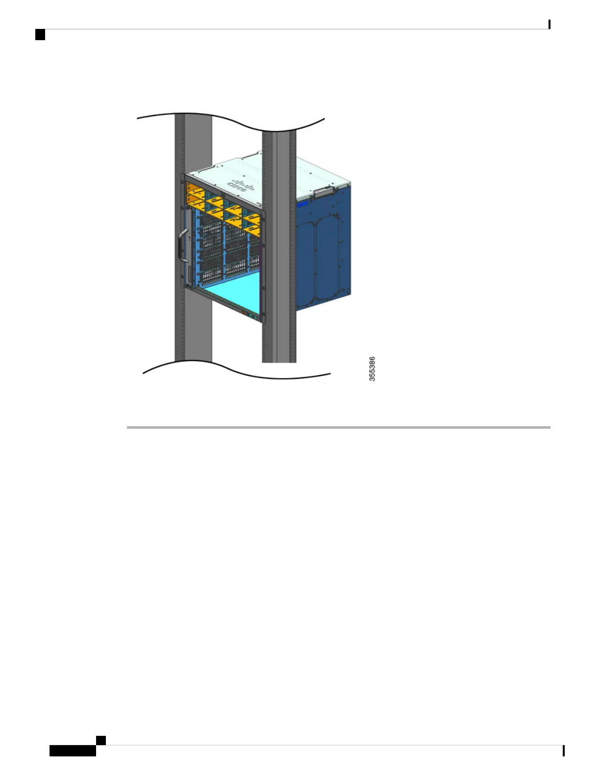
Figure 9: Chassis Secured to the Rack Posts
Step 4 4. Use a tape measure and level to ensure that the chassis is installed straight and level..
What to do next
After installing the chassis in its location, complete the installation process by:
1. Connecting the chassis to system ground.
2. Installing and connecting the power supplies to the power source.
3. Connecting the network interface cables to the supervisor module and line card modules. This may involve
installing transceivers before you attach the network interface cables.
4. Powering up the chassis and verifying the installation.
Cisco Catalyst 9400 Series Switches Hardware Installation Guide
52
Installing the Switch
Rack-Mounting the Chassis as Shipped

Table of Contents

Other manuals for Cisco Catalyst 9400 Series

Questions and Answers:

Question and Answer IconNeed help?

Do you have a question about the Cisco Catalyst 9400 Series and is the answer not in the manual?

Cisco Catalyst 9400 Series Specifications

General IconGeneral
SeriesCatalyst 9400 Series
Form FactorRack-mountable
Operating SystemCisco IOS XE
Uplink Options40G and 100G uplinks
StackingNot supported
Layer SupportLayer 2 and Layer 3
Operating Temperature0°C to 40°C (32°F to 104°F)
Storage Temperature-40°C to 70°C (-40°F to 158°F)
Humidity5% to 90% noncondensing
Power Supply OptionsAC and DC power supplies
RedundancyPower supply, supervisor engine
Modular Slots7 or 10
MAC Address Table Size256, 000
Security FeaturesACLs, TrustSec, MACsec
ManagementCLI, SNMP, NETCONF, RESTCONF, Cisco DNA Center

Related product manuals