Network Module Link StatusColor
Link is off due to a fault or because it has exceeded a limit set in the switch software.
Link faults occur when noncompliant cabling is connected to an SFP/SFP+/SFP28
port. Use only standard-compliant cabling to connect to Cisco SFP/SFP+/SFP28
ports. You must remove from the network any cable or device that causes a link
fault.
Caution
Blinking amber
Link for the SFP/SFP+/SFP28 has been disabled.Amber
Rear Panel
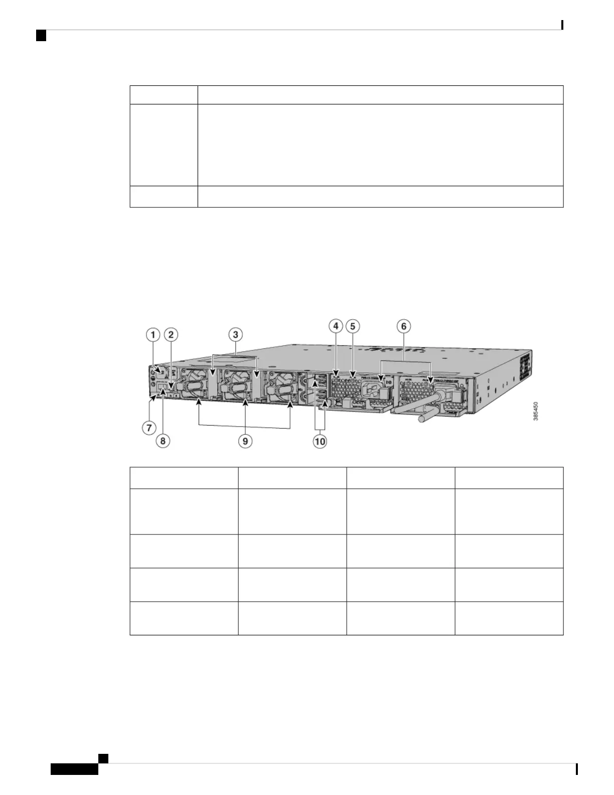
The switch rear panel includes StackWise connectors, StackPower or XPS connectors, ports, fan modules,
and power supply modules.
Figure 6: Switch Rear Panel
Power supply modules6USB3.0–SSD port1
BEACON LED7MGMT (RJ-45
10/100/1000 management
port)
2
CONSOLE (RJ-45
console port)
8StackWise-480 port
connectors
3
Fan modules9AC OK (input) status
LED
4
StackPower connectors10PS OK (output) status
LED
5
RFID Tag
The chassis has a built-in,passive RFID tag that uses UHF RFID technology and requires an RFID reader
with compatible software. It provides auto-identification capabilities for asset management and tracking. The
Cisco Catalyst 9300 Series Switches Hardware Installation Guide
14
Product Overview
Rear Panel