48-Port Switch
4
24-Port SwitchPoE Option
These are the combinations of
power supplies:
• (1) 1100 W + (1) 715 W
• (2) 1100 W
Up to 30 PoE ports can
receive full Cisco UPoE.
Note
(2) 1100 WCisco UPoE (up to 60 W per port)
4
A 48-port switch with one 715-W power supply provides up to 8.7 W of PoE to all ports.
The power supply modules have two status LEDs.
Table 14: Switch Power Supply Module LEDs
DescriptionPS OKDescriptionAC OK
Output is disabled, or input is outside
operating range (AC LED is off).
OffNo AC input power.Off
Power output to switch active.GreenAC input power present.Green
Output has failed.Red
Fan Module
The switch supports three internal hot-swappable 12-V fan modules (FAN-T2=) are available. The air circulation
system consists of the fan modules and the power supply modules. The airflow patterns vary depending on
the power supply configuration.
When the fan modules are operating properly, a green LED at the top left corner of the fan assembly (viewed
from the rear), is ON. If the fan fails, the LED turns to amber. The switch can operate with two operational
fans, but the failed fan should be replaced as soon as possible to avoid a service interruption due to a second
fan fault.
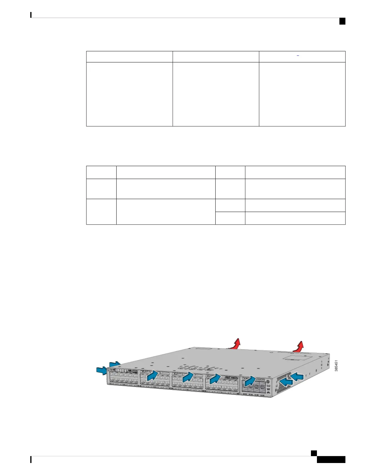
Figure 7: Switch Airflow Patterns
The following illustration shows the airflow pattern for the switches. The blue arrow shows cool airflow, and
the red arrow shows warm airflow.
For information about installing a fan module and fan specifications, see Installing a Fan Module, on page
64.
Cisco Catalyst 9300 Series Switches Hardware Installation Guide
17
Product Overview
Fan Module