StackPower Connector
The switches have a StackPower connector for use with Cisco StackPower cables to configure a switch power
stack that includes up to four switches. A switch power stack can be configured in redundant or power-sharing
mode.
You can order these StackPower cables from your Cisco sales representative:
• CAB-SPWR-30CM (0.3-meter cable)
• CAB-SPWR-150CM (1.5-meter cable)
For details about connecting StackPower cables and StackPower guidelines, see Planning a StackPower Stack,
on page 29.
Ethernet Management Port
You can connect the switch to a host such as a Windows workstation or a terminal server through the
10/100/1000 Ethernet management port or one of the console ports. The 10/100/1000 Ethernet management
port is a VPN routing/forwarding (VRF) interface and uses a RJ-45 crossover or straight-through cable.
The 10/100/1000 Ethernet management port is an RJ-45 connector that should be connected to a Windows
workstation or a terminal server. Do not connect this port to another port in the same switch or to any port
within the same switch stack.
Note
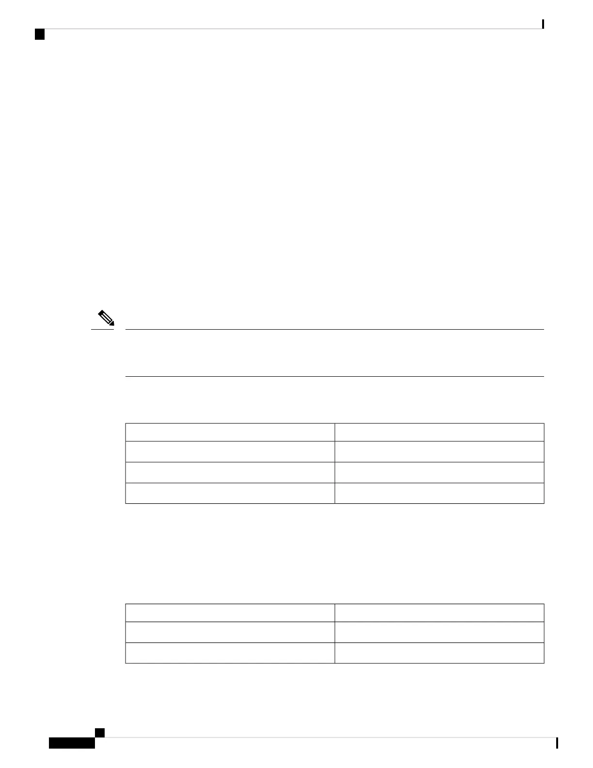
The following table shows the Ethernet management port LED colors and their meanings.
Table 15: Ethernet Management Port LED
DescriptionColor
Link up but no activity.Green
Link up and activity.Blinking green
Link down.Off
RJ-45 Console Port
The RJ-45 console port connection uses the supplied RJ-45-to-DB-9 female cable.
The following table shows the RJ-45 console port LED colors and their meanings.
Table 16: RJ-45 Console LED
DescriptionColor
RJ-45 console port is active.Green
The port is not active.Off
Cisco Catalyst 9300 Series Switches Hardware Installation Guide
18
Product Overview
StackPower Connector