On some SFP/SFP+/SFP28 modules, the send and receive (TX and RX) markings might be shown by arrows
that show the direction of the connection.
Step 3 If the SFP/SFP+/SFP28 module has a bale-clasp latch, move it to the open, unlocked position.
Step 4 Align the module in front of the slot opening, and push until you feel the connector snap into place.
Figure 25: Installing an SFP/SFP+/SFP28 Module in the Network Module
Step 5 If the module has a bale-clasp latch, close it to lock the SFP/SFP+/SFP28 module in place.
Step 6 Remove the SFP/SFP+/SFP28 dust plugs and save.
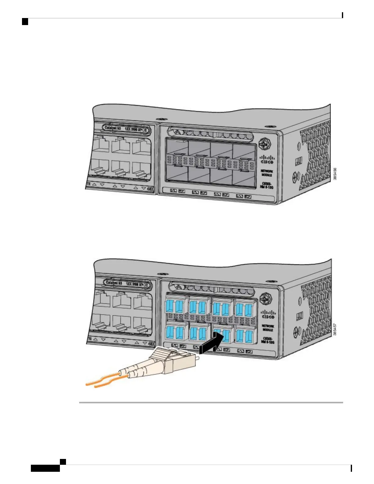
Step 7 Connect the SFP/SFP+/SFP28 cables.
Figure 26: Network Module with SFP/SFP+/SFP28 Modules Installed
Cisco Catalyst 9300 Series Switches Hardware Installation Guide
52
Installing a Network Module
Installing SFP, SFP+ and SFP28 Modules