2-9
User Guide for the Catalyst Express 500 Switches
OL-8122-01
Chapter 2 Setup and Installation
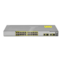
Install the Switch
Installation Guidelines
When deciding where to place the switch, be sure to observe these requirements:
• Cabling is away from sources of electrical noise, such as radios, power lines,
and fluorescent lighting fixtures.
• Clearance to front and rear panels is such that
–
Airflow around the switch and through the vents is unrestricted.
–
Front-panel LEDs can be easily read.
–
Access to ports is sufficient for unrestricted cabling.
–
AC power cord can reach from the AC power outlet to the connector on
the switch rear panel.
• Temperature does not exceed 113°F (45°C), humidity does not exceed
85 percent, and altitude at the installation site is not greater than 10,000 feet
(3049 m).
If the switch is installed in a closed or multirack assembly, the temperature
around it might be greater than normal room temperature.
• For copper Ethernet ports, cable lengths from the switch to connected devices
can be up to 328 feet (100 meters).
• For SFP module cable lengths, see Table A-2 and the documentation that
shipped with the module.