The illustrations in this document show all available connections for the access point. Unused connections
are capped with a connector plug to ensure the dust/watertight integrity of the access point. See the "Working
with the Access Cover" section for further details.
Note
Internal Connectors
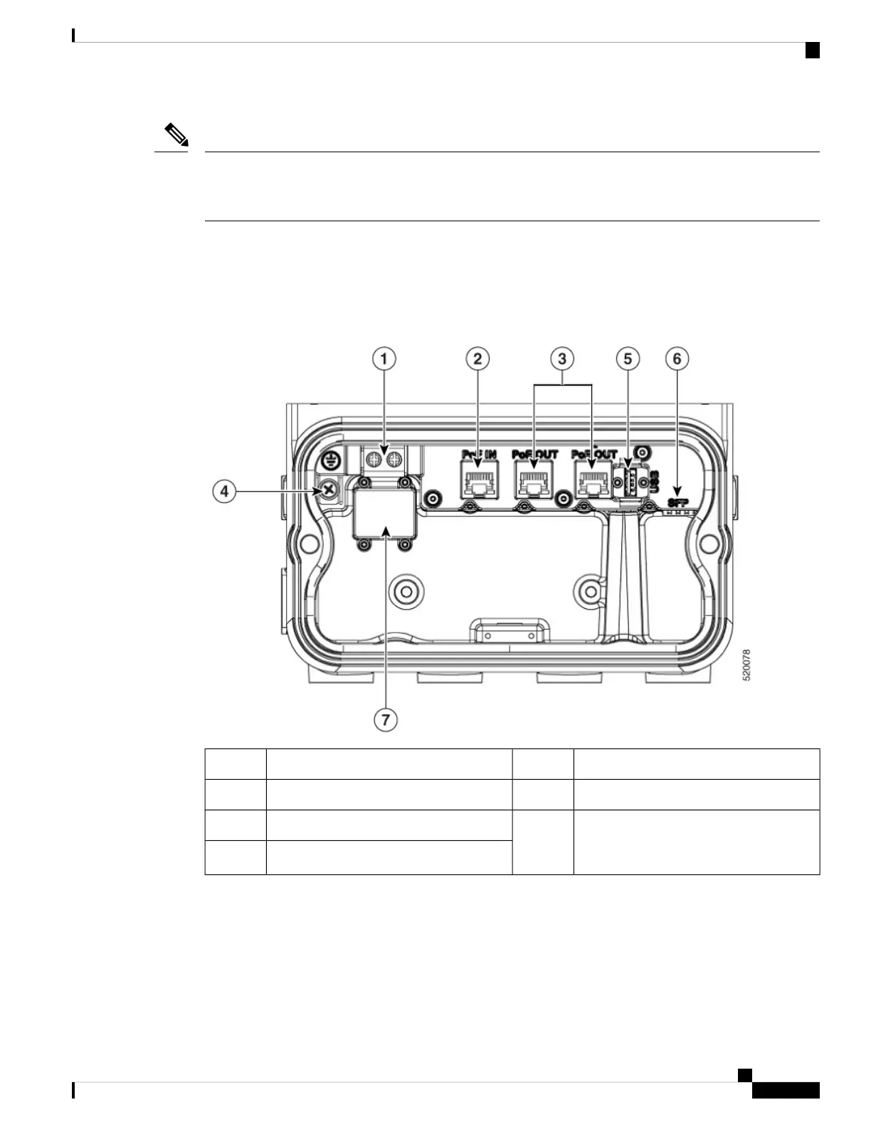
The following figure shows the IW-6300H Access Point Internal Connectors.
Figure 2: IW-6300H Access Point Internal Connectors
USB port5Power-IN (IW-6300H-DC-X-K9)1
SFP port6PoE In port2
Terminal block location of
IW-6300H-AC-X-K9 and
IW-6300H-DCW-X-K9
7PoE Out port3
Internal ground4
Console Port and Reset Button
The console port and reset button are under a covering M25 plug located on the side of the access point, as
shown in the following figure.
Cisco Catalyst IW6300 Heavy Duty Series Access Point Hardware Installation Guide
5
Overview
Internal Connectors

 Loading...