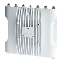
Figure 5: Power Connector of Access Point Model IW-6300H-DCW-x–K9
Internal ground2DC Power-IN1
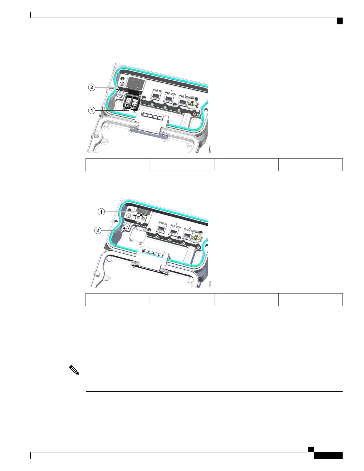
The following figure shows the power connector of access point model IW-6300H-DC-x-K9.
Figure 6: Power Connector of Access Point Model IW-6300H-DC-x–K9
Internal ground2DC Power-IN1
Antenna Ports
The access point antenna N-type connectors are located on the top of each model (see the following figure).
The supported antennas can be directly attached to the access point or remotely located. When used in a Class
1, Zone 2, Division 2 hazardous location, this equipment must be mounted with proper RF cables (if required)
and electrical wiring methods that comply with the governing electrical codes.
Antenna caps must be installed when an antenna is not in use (maximum torque range: 6.2-9.7 in-lbs).
Note
Cisco Catalyst IW6300 Heavy Duty Series Access Point Hardware Installation Guide
7
Overview
Antenna Ports

 Loading...