1-4
Cisco 1800 Series Integrated Services Routers (Fixed) Hardware Installation Guide
OL-6425-03
Chapter 1 Overview
Hardware Features
• DRAM—Stores the running configuration and routing tables and is used for packet buffering by the
network interfaces. Cisco
IOS software executes from DRAM memory.Cisco 1800 series
fixed-configuration routers contain 128 MB of internal DRAM memory by default. Cisco
1800
series fixed-configuration router models also contain a single 200-pin DDR Small Outline DIMM
(SODIMM) slot that can accommodate up to a 256-MB SODIMM, for a maximum of 384
MB of
internal DRAM memory.
• NVRAM—Internal flash memory. Stores the bootstrap program (ROM monitor), the configuration
register, and the startup configuration. All Cisco
1800 series fixed-configuration models contain 2
MB of boot/NVRAM memory by default.
• Flash memory—External CompactFlash memory. Stores the operating system software image. All
Cisco
1800 series fixed-configuration models contain 32 MB of internal flash memory by default,
and can use external CompactFlash cards up to 128 MB in capacity.
Power
Table 1-2 summarizes the AC power options for the Cisco 1800 series fixed-configuration routers.
LED Indicators
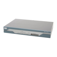
Table 1-3 summarizes the LED indicators that are located in the router front panel.
Ta b l e 1-2 Summary of Power Options for Cisco 1800 Series Fixed-Configuration Routers
Power Option Input IP Phone Power Output
AC input without inline power output 100–120V/200–240V, 1.2A/0.6A None
AC input with inline power output 100–120V/200–240V, 1.2A/0.6A –48 VDC, 80W
Ta b l e 1-3 Summary of LED Indicators on the Cisco 1800 Series Fixed-Configuration Routers
LED Color Description
SYS OK Green The router has successfully booted up, and the software is functional. This LED blinks while
booting or while in the ROM monitor mode.
WLAN Green This LED shows wireless access point link status. It is active only on wireless models.
On indicates that at least one client is associated.
Blinking green indicates that no client is associated.
POE
1
Green/
Amber
Green indicates that the inline power supply is present.
Amber indicates a fault with the inline power supply.
Off indicates that the inline power supply is not installed.
FE <port number> Green These LEDs indicate Fast Ethernet port link and status for both FE WAN ports (ports 0 and 1
on the Cisco
1811 and Cisco 1812 routers; port 0 on the Cisco 1801, Cisco 1802, and
Cisco
1803 routers) and the FE switch ports (ports 2 through 9 on the Cisco 1811 and
Cisco
1812 routers; ports 1 through 8 on the Cisco 1801, Cisco 1802, and Cisco 1803routers).
Green indicates a successful FE link.
Off indicates no link.
 Loading...
