1-9
Cisco 1800 Series Integrated Services Routers (Fixed) Hardware Installation Guide
OL-6425-03
Chapter 1 Overview
Chassis Views
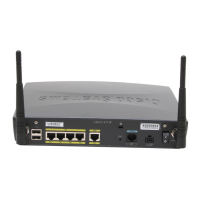
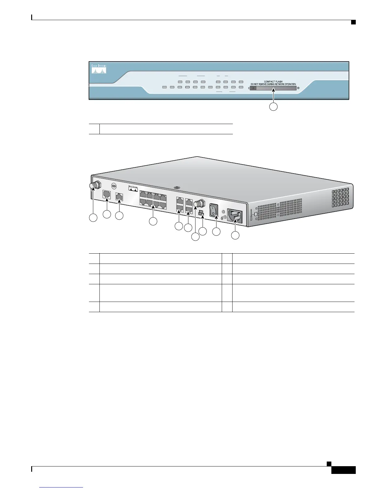
Figure 1-7 Front Panel of Cisco 1803 Router
Figure 1-8 Back Panel of Cisco 1803 Router
Cisco 1811 Chassis
Figure 1-9 shows the front panel of a Cisco 1811 router. Figure 1-10 shows the rear panel of a
Cisco 1811 router.
1 CompactFlash Slot
127447
SYS OK
POE
4 3
FEX
2
1 FE0
LINK
B1
ISDN
B2 CF
8
7 6
SWITCH
5
CO LPBK
PPP VPN
Cisco 1800
Series
DSL
1
1 G.SHDSL WAN port 6 POE connector
1
1. Inline power is a field-upgradable option only. It is not installed by default.
2 ISDN BRI S/T port 7 Power switch
3 Managed 8-port FE switch 8 Power connector
4
FE WAN port
2
2. The Cisco 1803 only has one FE WAN port, which is the lower of the two ports shown. The upper port is disabled, and
reserved for a future purpose.
9
RP-TNC antenna connectors (wireless models
only)
5 Console and AUX ports
127446
C
IS
C
O
18
01
1
2
3
4
5
6
7
8
9
9
 Loading...