1-5
Cisco 1800 Series Integrated Services Routers (Fixed) Hardware Installation Guide
OL-6425-03
Chapter 1 Overview
Hardware Features
For LED troubleshooting information, including possible trouble causes and corrective actions, see
Table 6-1 in the “Troubleshooting” chapter.
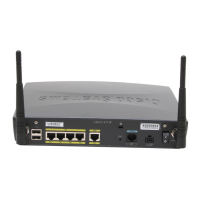
Integrated 802.11a/b/g Radio Module (Wireless Models Only)
The Cisco 1800 series fixed-configuration routers with the wireless option have an integrated IEEE
802.11a/b/g radio module that operates as a wireless access point in infrastructure mode. The wireless
routers have two reverse-polarity threaded Neill-Concelman (RP-TNC) connectors on the back panel. The
dipole swivel antennas that were shipped with the router connect to the RP-TNC connectors to operate the
802.11a/b/g radio module.
CD
2
Green This LED indicates whether a connection is established (carrier detect). On the Cisco 1801,
Cisco
1802, and Cisco 1803 routers, this LED indicates whether a DSL connection is
established. On the Cisco
1811 router, this LED indicates whether a modem connection is
established.
On indicates a connection is established.
Off indicates no connection established.
LPBK
3
Green On indicates the DSL interface is in loopback mode.
Off indicates DSL interface normal operation.
PPP Green On if at least one PPP connection is established.
VPN Green On if at least one VPN tunnel is established.
LINK
4
Green On indicates that an ISDN S/T connection has been established.
Off indicates that no ISDN S/T connection has been established.
B1
4
Green Blinking green indicates activity on the first B channel.
Off indicates no activity on the first B channel.
B2
4
Green Blinking green indicates activity on the second B channel.
Off indicates no activity on the second B channel.
SPD
5
Green On indicates a connection at high speed (V.90/V.92).
Off indicates a connection at low speed (V.32/V.32b/V.34).
BUSY
5
Green Blinking green indicates activity over the modem line.
Off indicates no activity.
CF Green On when CompactFlash memory is busy. Do not remove CompactFlash memory when this
light is on.
1. Inline power is a field-upgradable option only. It is not installed by default.
2. This LED does not exist on the Cisco 1812.
3. This LED exists on the Cisco 1801, Cisco 1802, and Cisco 1803 only.
4. This LED does not exist on the Cisco 1811.
5. This LED exists on the Cisco 1811 only.
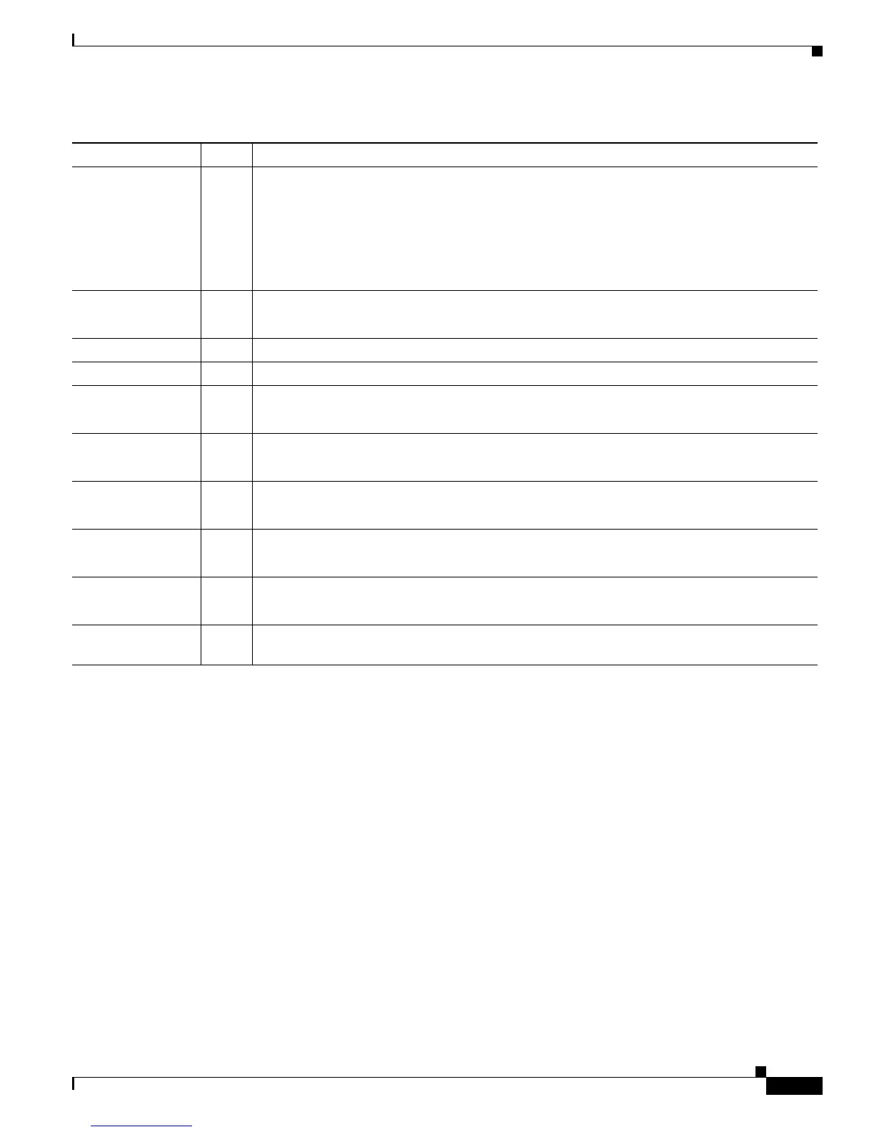
Table 1-3 Summary of LED Indicators on the Cisco 1800 Series Fixed-Configuration Routers (continued)
LED Color Description
 Loading...