1-10
Cisco 1800 Series Integrated Services Routers (Fixed) Hardware Installation Guide
OL-6425-03
Chapter 1 Overview
Chassis Views
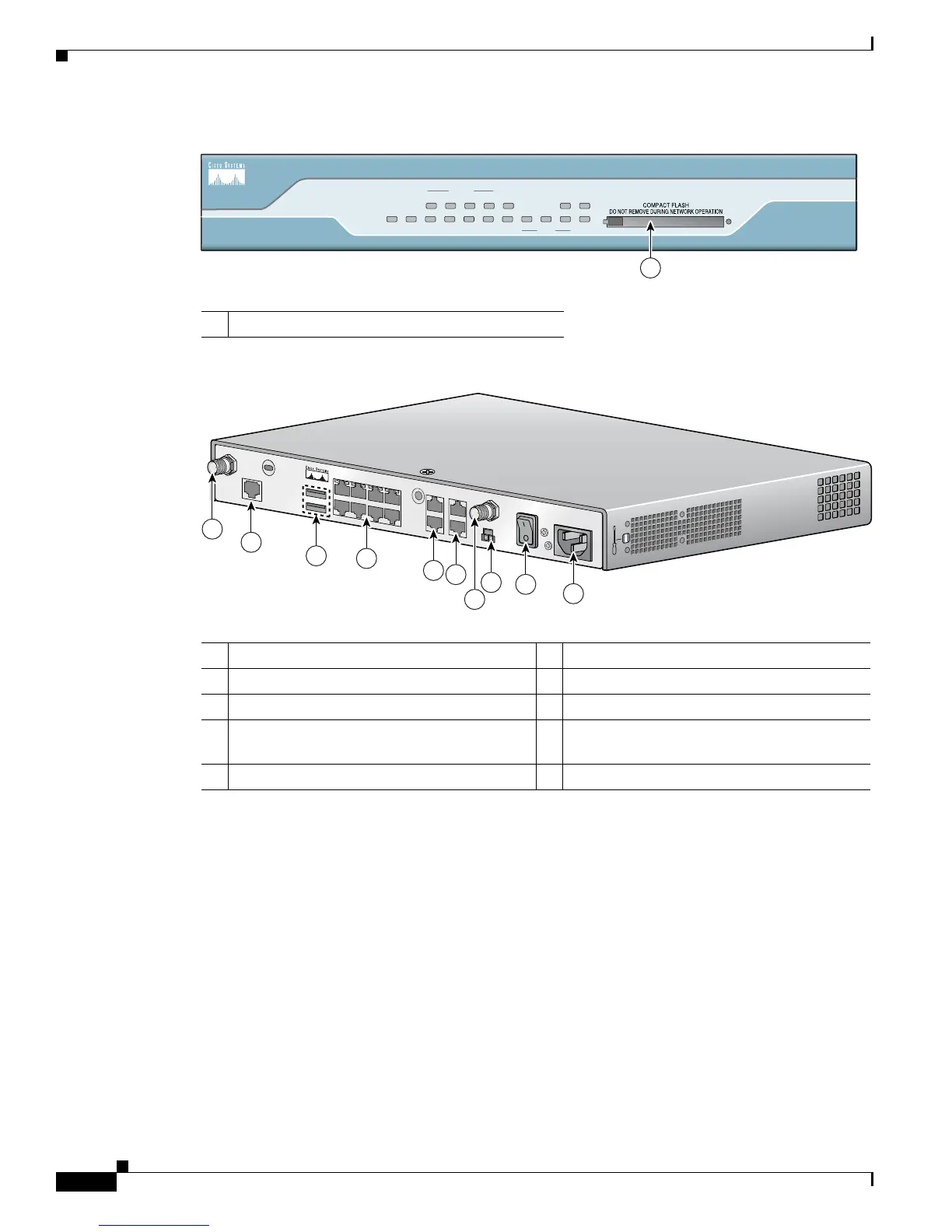
Figure 1-9 Front Panel of Cisco 1811 Router
Figure 1-10 Back Panel of Cisco 1811 Router
Cisco 1812 Chassis
Figure 1-11 shows the front panel of a Cisco 1812 router. Figure 1-12 shows the back panel of a
Cisco 1812 router.
1 CompactFlash Slot
SYS OK
POE
5 4
FEX
3
2
FE0
CD
SPD
V.92
BUSY CF
9
8 7
SWITCH
6
FE1
PPP VPN
Cisco 1800
Series
127448
1
1 V.92 Modem port 6 POE connector
1
1. Inline power is a field-upgradable option only. It is not installed by default.
2 USB 2.0 ports 7 Power switch
3 Managed 8-port FE switch 8 Power connector
4
FE WAN ports
9
RP-TNC antenna connectors (wireless models
only)
5 Console and AUX ports
 Loading...