3-3
Cisco 1800 Series Integrated Services Routers (Fixed) Hardware Installation Guide
OL-6425-03
Chapter 3 Chassis Installation Procedures
Installing the Chassis Ground Connection
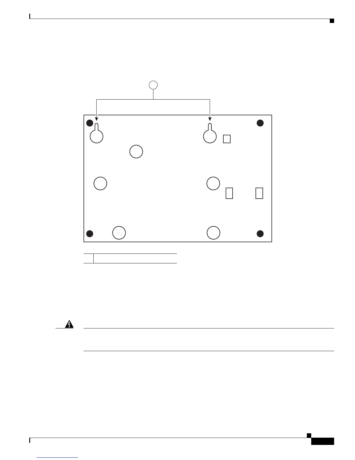
Figure 3-1 shows the underside of a Cisco 1800 series fixed-configuration router and the locations of the
wall-mount holes.
Figure 3-1 Mount Holes on Underside of Cisco 1800 Series Fixed-Configuration Router Chassis
After you install the router, you must connect the chassis to a reliable earth ground. For the chassis
ground connection procedures, see the
“Installing the Chassis Ground Connection” section on page 3-3.
Installing the Chassis Ground Connection
Warning
This equipment must be grounded. Never defeat the ground conductor or operate the equipment in the
absence of a suitably installed ground conductor. Contact the appropriate electrical inspection
authority or an electrician if you are uncertain that suitable grounding is available.
Statement 1024
You must connect the chassis to a reliable earth ground; the ground wire must be installed in accordance
with local electrical safety standards.
• For NEC-compliant grounding, use size 14 AWG (2 mm
2
) or larger copper wire and an appropriate
user-supplied ring terminal with an inner diameter of 1/4 inch (5 to 7 millimeters).
• For EN/IEC 60950–compliant grounding, use size 18 AWG (1 mm
2
) or larger copper wire and an
appropriate user-supplied ring terminal.
Follow these steps to install the ground connection:
1 Holes for wall-mounting
 Loading...