You can fit four copper SFPs in either the top row of ports or the bottom row of ports. Both rows cannot
be populated at the same time, because the SFP ports are too close together for the copper SFPs to fit on
both the top and the bottom row at the same time. For a list of copper SFPS, see Supported SFP/SFP+
Transceivers, on page 21.
Note
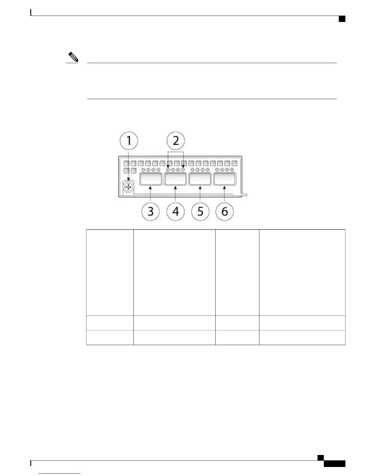
The following figure shows the front panel view of the 40G network module.
Figure 8: Firepower Network Module 40G
Network activity LEDs
• Unlit – No connection or port
is not in use.
• Solid amber – No link or
network failure.
• Solid green – Link up.
• Blinking green – Network
activity.
2Captive screw/handle1
Ethernet X/2
4
Ethernet X/1
3
Ethernet X/4
6
Ethernet X/3
5
For More Information
•
See Hardware Bypass (FTW) Network Modules, on page 12 for the location and description of
the LEDs, and the port configurations for the hardware bypass network modules.
•
See Remove and Replace the Network Module, on page 59 for the procedure for removing and
replacing network modules.
Cisco Firepower 4100 Series Hardware Installation Guide
11
Overview
Nonhardware (FTW) Bypass Network Modules

 Loading...


