Table 5: DC Power Supply Module Hardware Specifications
-40 to -60V DCInput voltage
26A (at 40V DC)
The power supply module is rated at 26A
but the system power is limited to 10A. See
Hardware Specifications, on page 34 for
more system specifications.
Note
Maximum current
950WMaximum output power
1+1 redundantRedundancy
92%Efficiency at 50% load
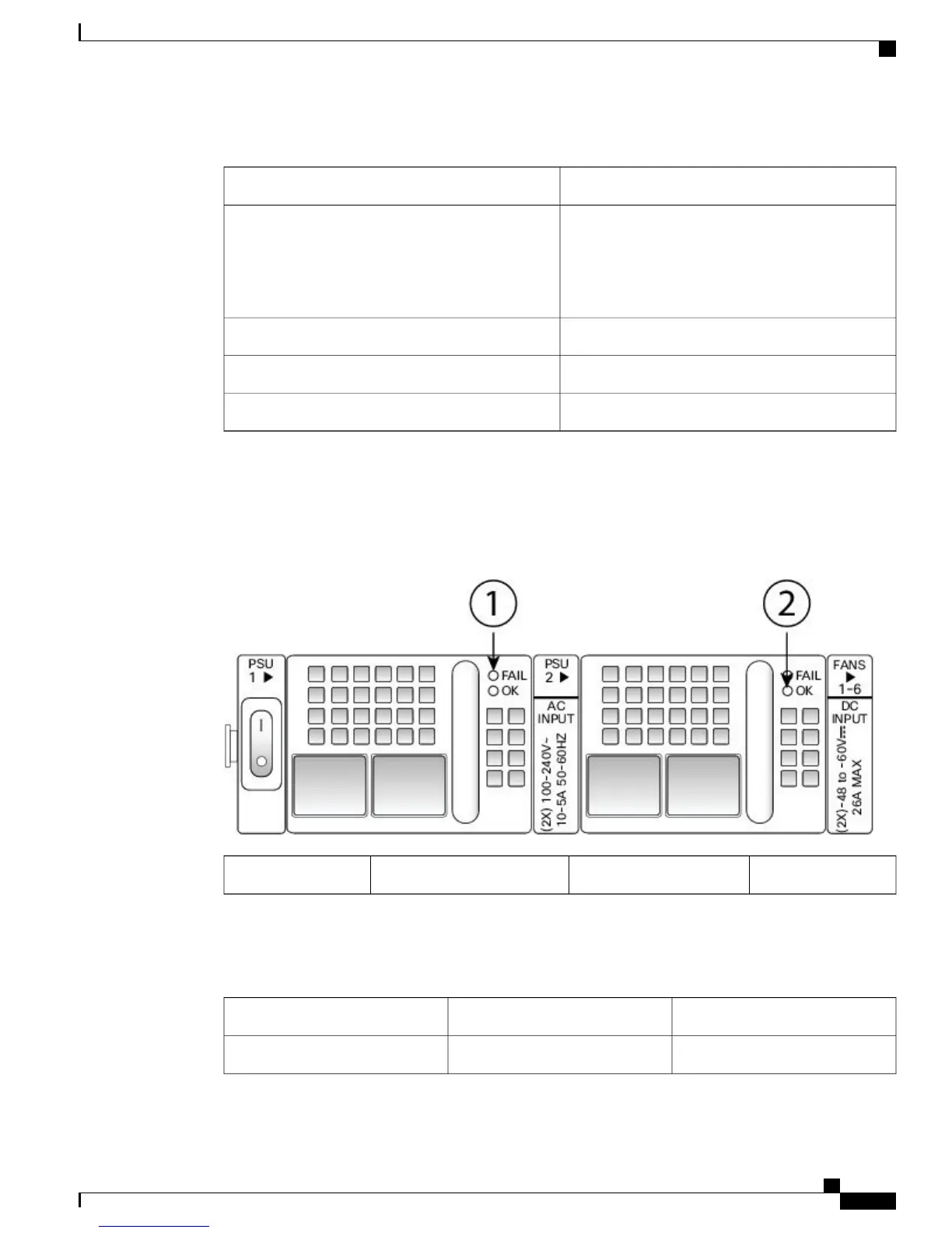
Power Supply Module LEDs
The following figure shows the bicolor power supply LEDs. The LEDs are located on the upper right side.
Figure 12: Power Supply Module LEDs
Green OK LED2Amber FAIL LED1
The following table describes the power module supply LEDs.
Table 6: Power Supply Module LEDs
Green LED (OK Status)Amber LED (Fail Status)
OffOffNo power to all power supplies
Cisco Firepower 4100 Series Hardware Installation Guide
19
Overview
Power Supply Modules
 Loading...


