OffOnPower supply module failure
Includes over voltage, over current,
over temperature, and fan failure
Off1 Hz blinkingPower supply module warning
events
Power supply continues to operate
(high temperature, high power, and
slow fan)
1 Hz blinkingOffPower present
3.3VSB on (power supply module
off)
OnOffPower supply module ok and on
Fan Modules
The Firepower 4100 security appliance requires six fan modules, which are hot-swappable. They are installed
in the rear of the chassis. The system supports operation with a single fan failure (N+1 fan redundancy), but
do not run the system for an extended amount of time without all fan modules installed. Keep removal and
replacement time at three minutes. Remove and replace one fan module at a time.
If you remove a fan or a fan fails, the other fans operate at full speed, which can be noisy.
The fan modules are numbered left to right, for example, FAN1, FAN2, FAN3, FAN4, FAN5, and FAN6.
See Remove and Replace the Fan Module, on page 62 for the procedure for removing and replacing the fan
module.
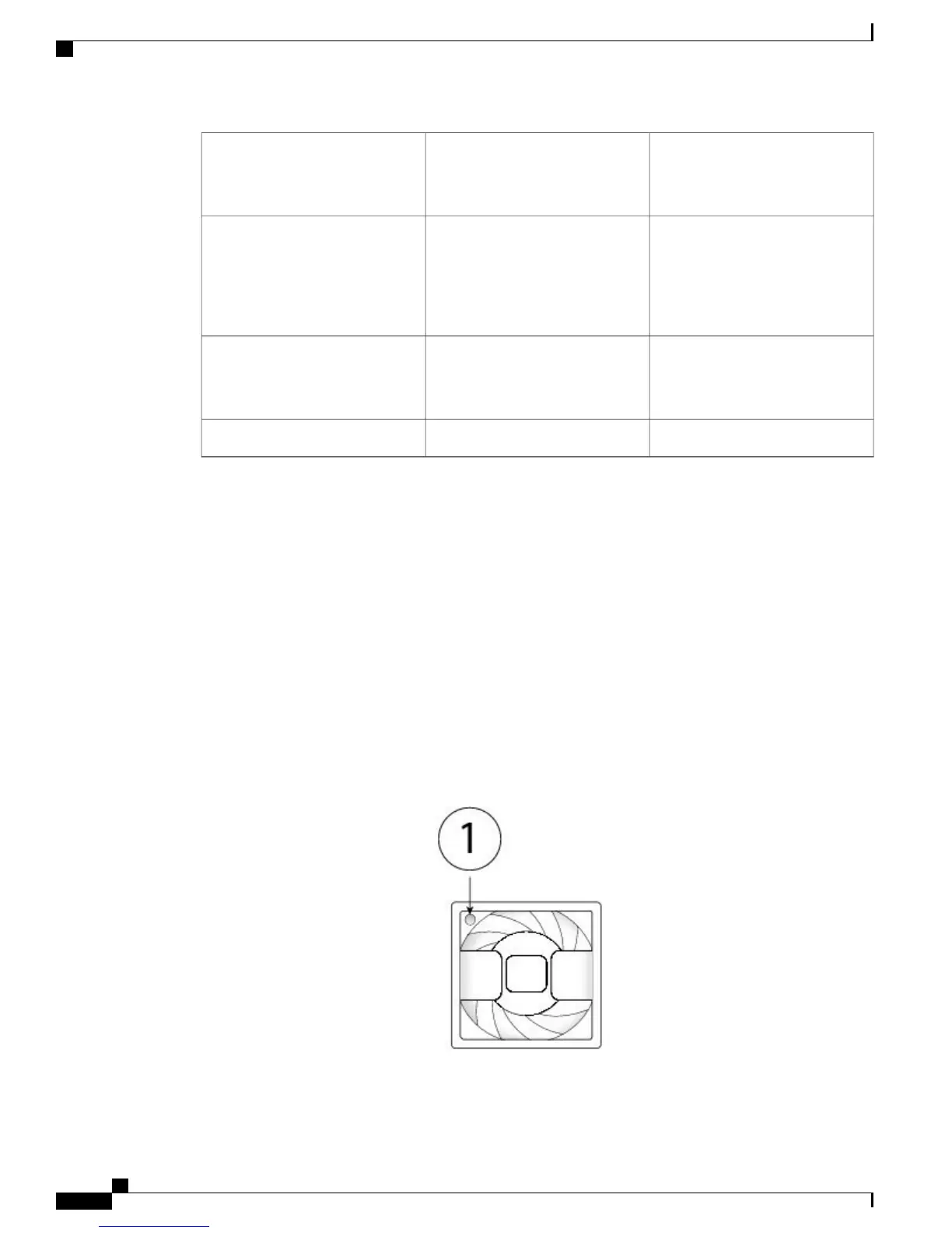
The following figure shows the location of the fan LED.
Figure 13: Fan LED
Cisco Firepower 4100 Series Hardware Installation Guide
20
Overview
Fan Modules
 Loading...


