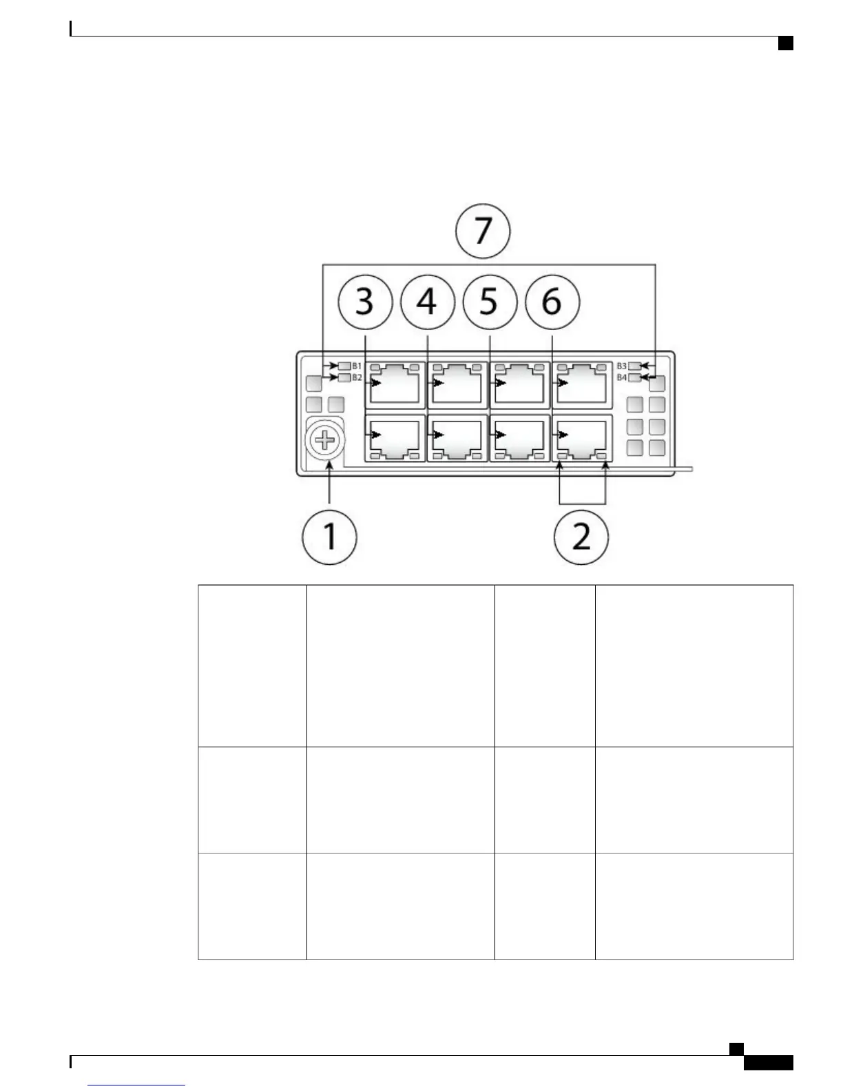
The following figure shows the front panel view of the 1G FTW network module. Pair ports 1 and 2, 3 and
4, 5 and 6, and 7 and 8 to form hardware bypass paired sets.
Figure 9: Firepower Network Module 1G with Hardware Bypass
Eight Network activity LEDs
• Left LED – Solid green
indicates network activity
when a 10M/100M/1G
connection is made.
• Right LED – Not in use at
this time.
2Captive screw/handle1
Ethernet X/2
Ports 3 and 4 are paired together to
form a hardware bypass pair. LED
B2 applies to this paired port.
4
Ethernet X/1
Ports 1 and 2 are paired together
to form a hardware bypass pair.
LED B1 applies to this paired
port.
3
Ethernet X/2
Ports 7 and 8 are paired together to
form a hardware bypass pair. LED
B4 applies to this paired port.
6
Ethernet X/2
Ports 5 and 6 are paired together
to form a hardware bypass pair.
LED B3 applies to this paired
port.
5
Cisco Firepower 4100 Series Hardware Installation Guide
13
Overview
Hardware Bypass (FTW) Network Modules
 Loading...


