Bypass LEDs B1 through B4
• Solid green – In Standby
mode.
• Blinking amber – Port is in
hardware bypass mode,
failure event.
• Solid amber – Port is in
hardware bypass mode,
forced.
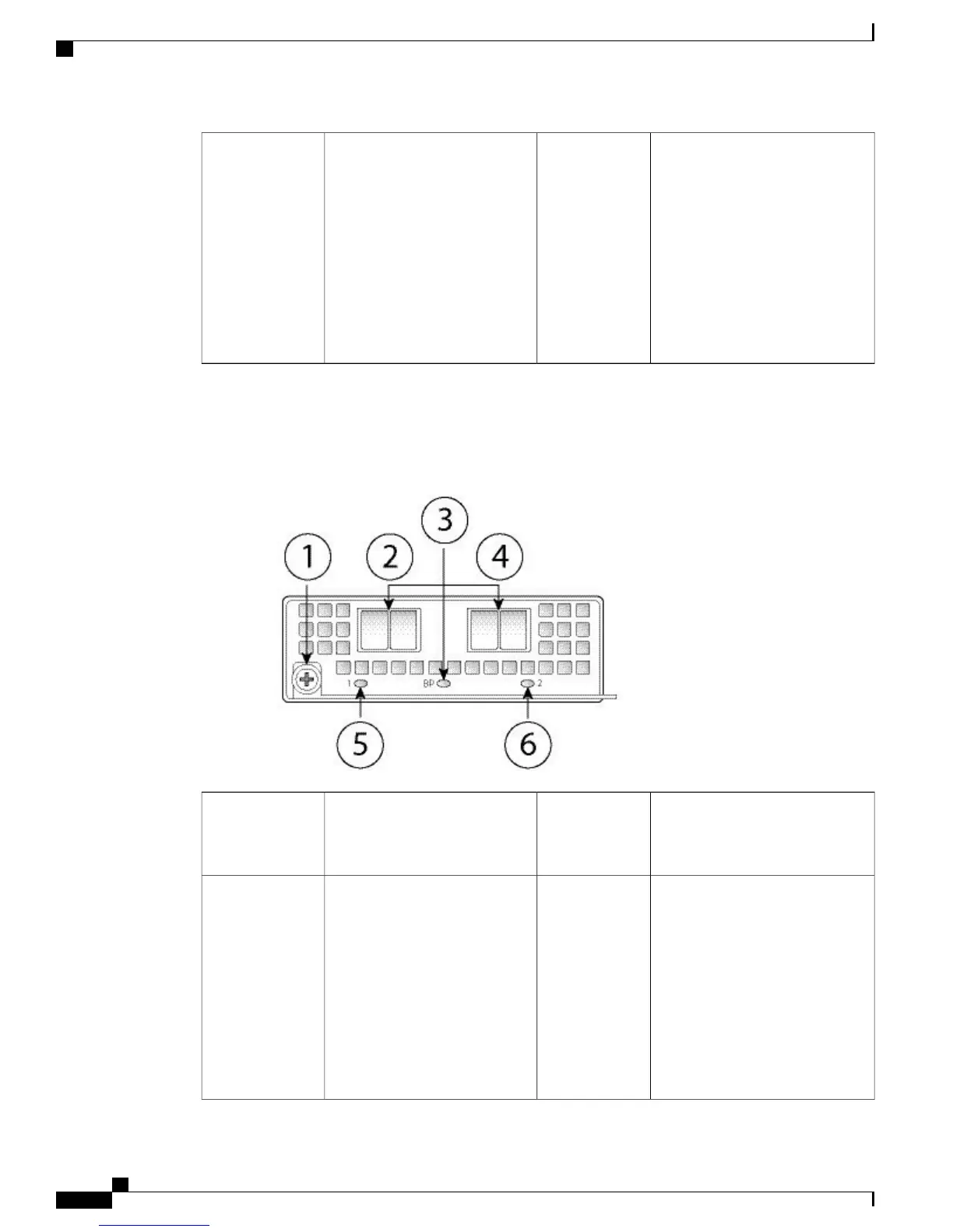
The following figure shows the front panel view of 40G FTW network module. Pair the two ports to create
a hardware bypass paired set.
Figure 10: Firepower Network Module 40G with Hardware Bypass
Ethernet X/1
Ports 1 and 2 are paired together to
form a hardware bypass pair.
2Captive screw/handle1
Ethernet X/2
Ports 1 and 2 are paired together to
form a hardware bypass pair.
4Bypass LED BP
• Solid green – In Standby
mode.
• Blinking amber – Port is in
hardware bypass mode,
failure event.
• Solid amber – Port is in
hardware bypass mode,
forced.
3
Cisco Firepower 4100 Series Hardware Installation Guide
14
Overview
Hardware Bypass (FTW) Network Modules
 Loading...


