Network activity LEDs
• Solid amber – No
connection, or port is not in
use, or no link or network
failure.
• Solid green – Link up, no
network activity.
• Blinking green – Network
activity.
5
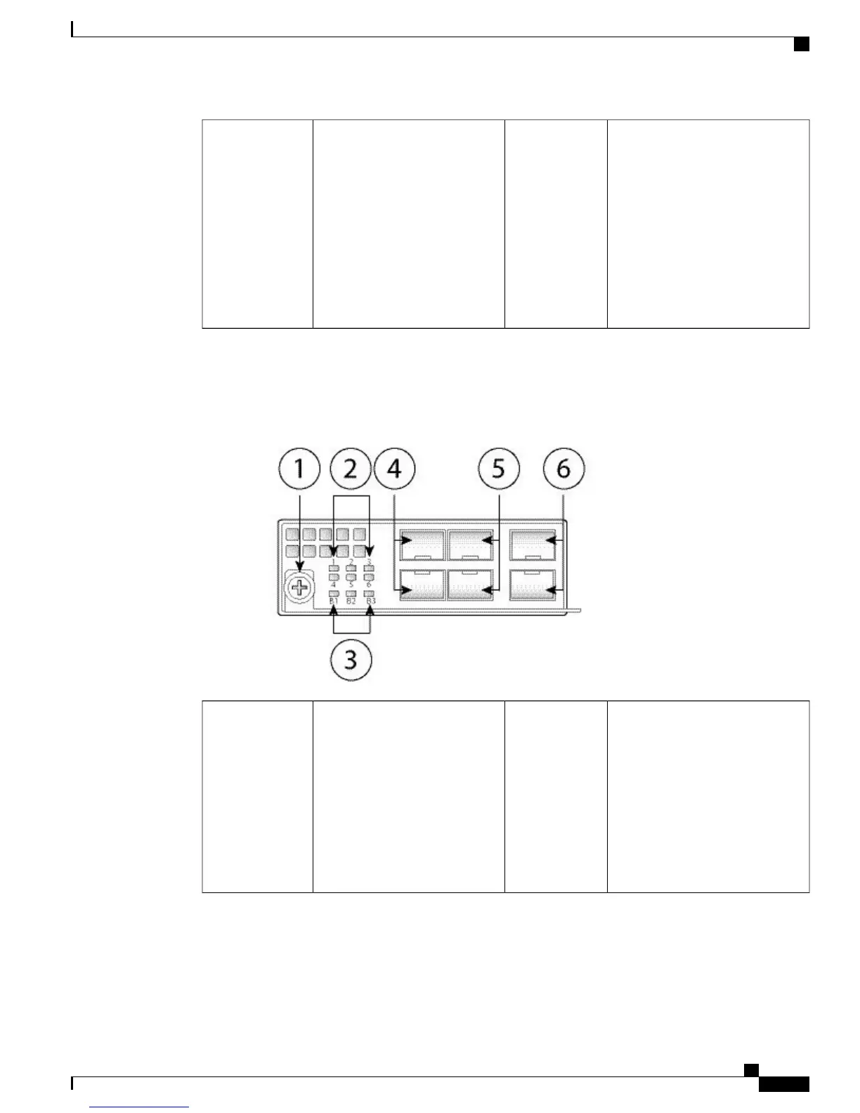
The following figure shows the front panel view of the 1G SX, 10G SR, and 10G LR FTW network module.
Pair ports 1 and 2, 3 and 4, and 5 and 6 to form hardware bypass paired sets.
Figure 11: Firepower Network Module 1G SX /10G SR/10G LR with Hardware Bypass
Six Network activity LEDs
• Solid amber – No connection,
or port is not in use, or no
link or network failure.
• Solid green – Link up, no
network activity.
• Blinking green – Network
activity.
2Captive screw/handle1
Cisco Firepower 4100 Series Hardware Installation Guide
15
Overview
Hardware Bypass (FTW) Network Modules
 Loading...


