1-16
Cisco IE 3000 Switch Hardware Installation Guide
Chapter 1 Overview
Front-Panel Description
100Base-FX Port Status LEDs
These LEDs display information about the individual ports. See Table 1-8.
Dual-Purpose Port LEDs
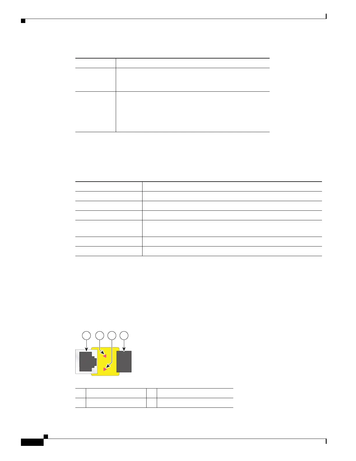
Figure 1-14 shows the LEDs on a dual-purpose port. You can configure each port as either a 10/100/1000
port through the RJ-45 connector or as an SFP module, but not both at the same time. The LEDs show
how the port is being used (Ethernet or SFP module).
The LED colors have the same meanings as described in Table 1-7.
Figure 1-14 Dual-Purpose Port LEDs
Alternating
green-amber
Link fault. Error frames can affect connectivity, and errors
such as excessive collisions, CRC errors, and alignment and
jabber errors are monitored for a link-fault indication.
Solid amber Port is not forwarding. Port was disabled by management, an
address violation, or STP.
Note After a port is reconfigured, the port LED can remain
amber for up to 30 seconds while STP checks the
switch for possible loops.
Table 1-7 10/100 Port Status LEDs (continued)
Color System Status
Table 1-8 100BASE-FX MM Uplink Port Status LEDs
Color System Status
Off No link.
Solid green Link is present.
Blinking green Activity. Port is sending or receiving data.
Blinking amber A link blocked by Spanning Tree Protocol (STP) is sending or receiving
data.
Alternating green-amber Link is faulty.
Solid amber Link is disabled.
1 RJ-45 connector 3 SFP module port in-use LED
2 RJ-45 port in-use LED 4 SFP module slot