37
Switch Installation
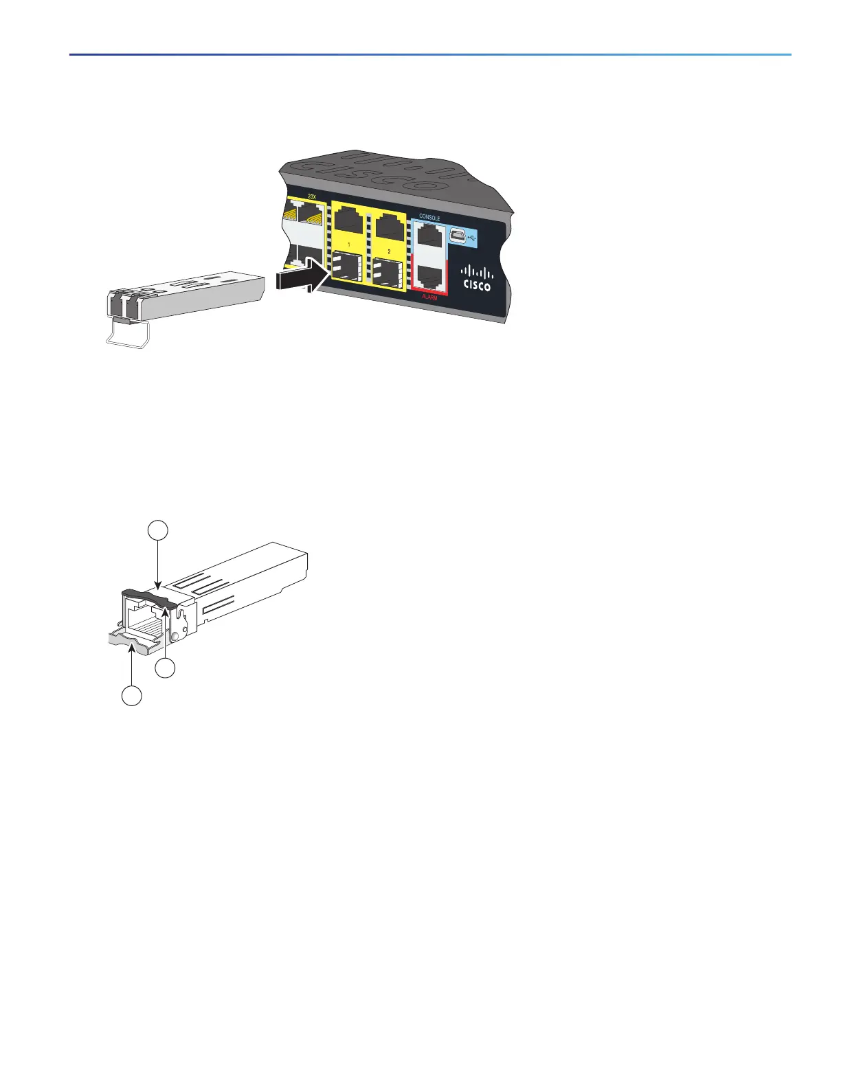
Installing and Removing SFP Modules
Figure 25 Installing an SFP Module
Caution: Do not remove the dust plugs from the fiber-optic SFP module port or the rubber caps from the fiber-optic
cable until you are ready to connect the cable. The plugs and caps protect the SFP module ports and cables from
contamination and ambient light.
Installing 1000BASE-T SFP Modules
The 1000BASE-T (copper) SFP transceiver, see Figure 26 on page 37, has a bale-clasp locking mechanism that secures
the transceiver in the module socket. The SFP network interface is an RJ-45 connector.
Figure 26 1000BASE-T SFP Transceiver
Caution: To comply with GR-1089 intrabuilding lightning immunity requirements, you must use grounded, shielded,
twisted-pair, CAT5 cabling.
Note: When connecting to a 1000BASE-T-compatible server, workstation, or router, use four twisted-pair,
straight-through CAT5 cabling for the SFP transceiver port. When connecting to a 1000BASE-T-compatible switch or
repeater, use four twisted-pair, crossover CAT5 cabling.
To install a 1000BASE-T SFP transceiver:
1. Attach an ESD-preventive wrist strap to your wrist and to the ESD ground connector on the chassis or to a properly
grounded bare metal surface.
1
RJ-45 connector
3
Bale-clasp latching mechanism in the open
(unlocked) position.
2
Bale-clasp latching mechanism in the closed
(locked) position.
 Loading...


