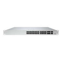
Note: The MS390 10G and 40G SFP+ and QSFP+ uplink modules are hot-swappable.
Stack Cabling Installation
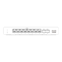
• Connect the cable to the stack port on the switch back panel (as shown in the back panel diagram). Align the
connector and connect the stack cable to the stack port on the switch back panel and finger-tighten the screws
(clockwise direction). Make sure the Cisco logo is on the top side of the connector.
• Connect the other end of the cable to the port on the other switch and finger-tighten the screws. Avoid over tightening
the screws.
Please refer to these instructions here before stacking MS390 out of the box.
StackPower Cabling Installation
• StackPower on MS390 supports a ring topology of up to 4 switches.
• Connect the end of the cable with a green band to either StackPower port on the first switch (see back panel diagram
to locate the StackPower ports). Align the connector correctly, and insert it into a StackPower port on the switch rear
panel.
• Connect the end of the cable with the yellow band to another switch. Hand-tighten the captive screws to secure the
StackPower cable connectors in place.
• StackPower feature doesn't need any dashboard configuration but is automatically enabled when the cables are
installed.
12
 Loading...