Step 4 Ensure that the lockout device is removed if installed and turn on the circuit breaker(s) to the shelf. Verify
that the Green LED on the PSU is on.
Connect DC Power to NCS 1001
NCS 1001 relies on the protective devices in the building installation to protect against short circuit, overcurrent,
and ground faults. Ensure that the protective devices comply with local and national electrical codes.
Caution
The system accepts a nominal input voltage of -48 VDC or -60 VDC at 15A, with an operational tolerance
range of -40.5 to -72 VDC. A dual pole breaker per each power feed is needed for the installation. The rating
of the breaker is 20A.
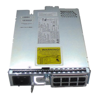
Figure 36: Hot Area on PSU Faceplate
Procedure
Step 1 Verify that the correct fuse panel is installed in the top mounting space.
Step 2 Measure and cut the cables as needed to reach NCS 1001 from the fuse panel.
Step 3 Dress the power according to local practice.
Step 4 Connect the office battery and return cables according to the fuse panel engineering specifications.
Step 5 Insert the DC connector into the DC receptacle on the power supply.
Hardware Installation Guide for Cisco NCS 1001
38
Install Cisco NCS 1001
Connect DC Power to NCS 1001
 Loading...
