•
The switch must be initially configured using a console.
Step 1
Connect the RJ-45, UTP cable to the MGMT ETH port on the switch.
Step 2
Connect the management cable into the management port on the switch. For shorter connections, you can use a cable
with RJ-45 connectors. For longer connections, you can use an optical cable with SFP transceivers (LH or SX type).
Use only one of these management ports—the switch does not support the use of both management
ports.
Note
Step 3
Connect the other end of the cable to a 10/100/1000 Ethernet port on a network device.
Step 4
Connect the other end of the cable to a 10/100/1000 or SFP port on a network device.
What to Do Next
You are ready to connect the interface ports on each of the line cards to the network.
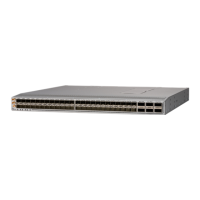
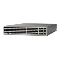
Uplink Connections
The six uplink ports support 40- and 100-Gigabit Ethernet using QSFP28 transceivers.
For a list of transceivers and cables used by this switch for uplink connections, see http://www.cisco.com/c/
en/us/support/interfaces-modules/transceiver-modules/products-device-support-tables-list.html.
Statement 1051—Laser Radiation
Invisible laser radiation may be emitted from disconnected fibers or connectors. Do not stare into beams
or view directly with optical instruments.
Warning
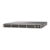
Downlink Connections
The Cisco Nexus 93180YC-FX switch has 48 downlink ports that connect to servers. Each of these ports
supports 1-, 10-, and 25-Gigabit speeds over optical cables.
For a listing of the transceivers and cables that the optical downlink ports support, see http://www.cisco.com/
c/en/us/support/interfaces-modules/transceiver-modules/products-device-support-tables-list.html
Cisco Nexus 93180YC-FX NX-OS Mode Switch Hardware Installation Guide
27
Connecting the Switch to the Network
Uplink Connections

 Loading...