4-17
Cisco Redundant Power System Hardware Installation Guide
OL-3654-01
Chapter 4 Connecting the Cisco RPS
Connecting Routers and the Cisco MC3810 Concentrator
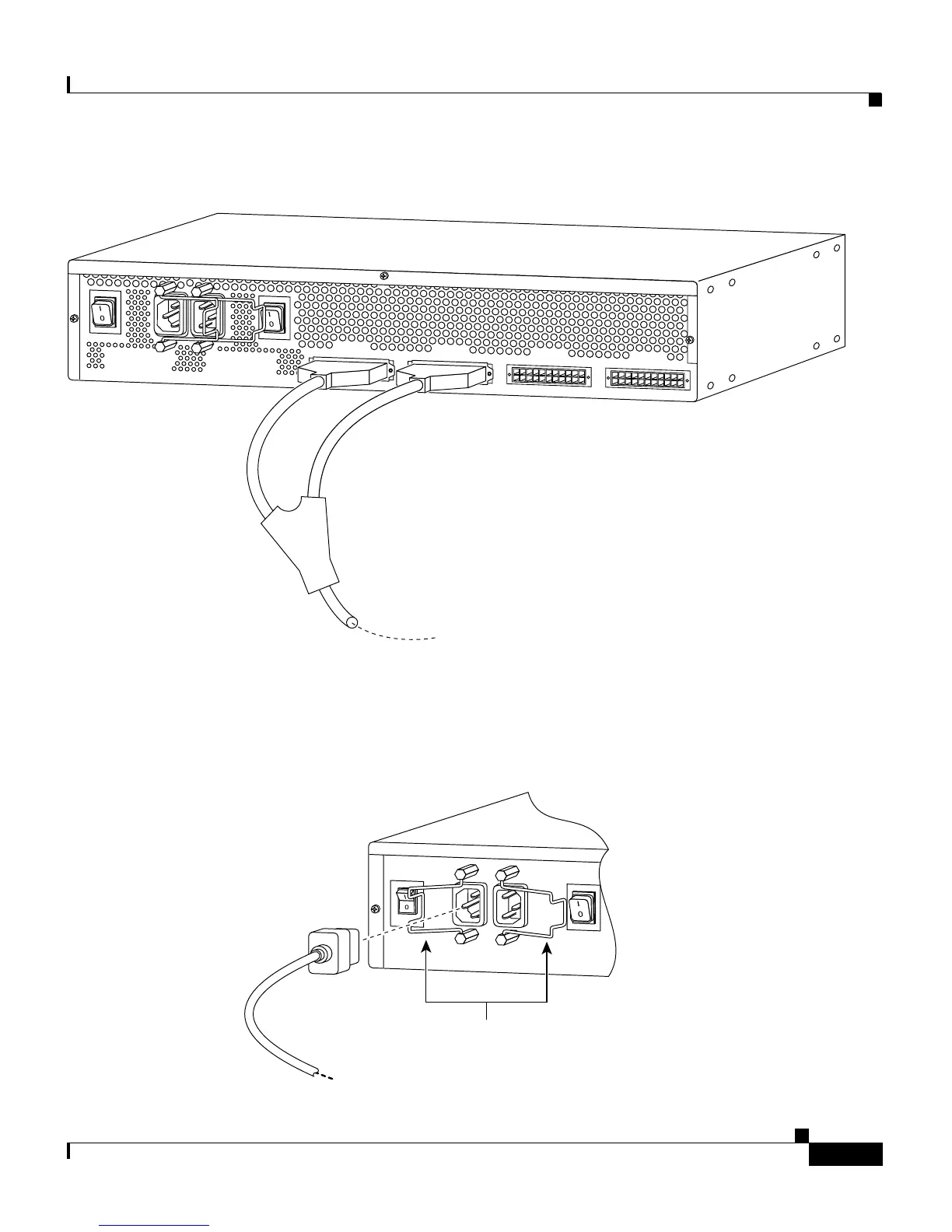
Figure 4-23 Connecting a Two-to-One Y-Cable for Fully Redundant Power
Step 4 On the rear panel of the Cisco RPS, connect an AC power cable to either or both
of the power connectors. Use the cable locks on the Cisco RPS to lock the cables
in place. (See Figure 4-24.)
Figure 4-24 Connecting the AC Power Cables to the Cisco RPS
29089
AC INPUT 1
100-200 V~ 50/60 Hz
10-5 A 1000 W
AC INPUT 2
100-200 V~ 50/60 Hz
10-5 A 1000 W
DC OUTPUT 1
DC OUTPUT 2
DC OUTPUT 3
DC OUTPUT 4
29092
Cable locks