Cisco UCS B200 M3 Blade Server
38
SUPPLEMENTAL MATERIAL
— Bank 1 - E1, F1, G1, and H1 (black DIMM slots)
— Bank 2 - E2, F2, G2, and H2 (white DIMM slots)
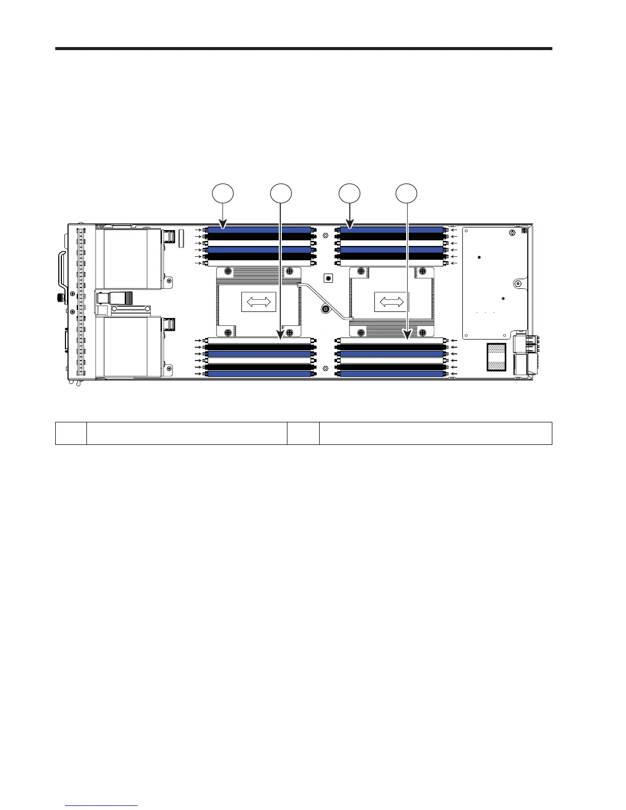
The DIMM and CPU physical layout is shown in Figure 7. The 12 DIMM slots at the left are controlled by CPU
1 and the 12 DIMM slots on the right are controlled by CPU 2.
Figure 7 DIMM and CPU Layout
1 Channels A-D for CPU 1 2 Channels E-H for CPU 2
31374
CPU 1
CPU 2
C0
C1
C2
D0
D1
D2
B2
B1
B0
A2
A1
A0
E0
E1
E2
F0
F1
F2
E0
E1
E2
F0
F1
F2
H2
H1
H0
G2
G1
G0
1 1 2 2
 Loading...