Cisco UCS C24 M3 High-Density SFF Rack-Mount Server
SUPPLEMENTAL MATERIAL
53
Rear Panel
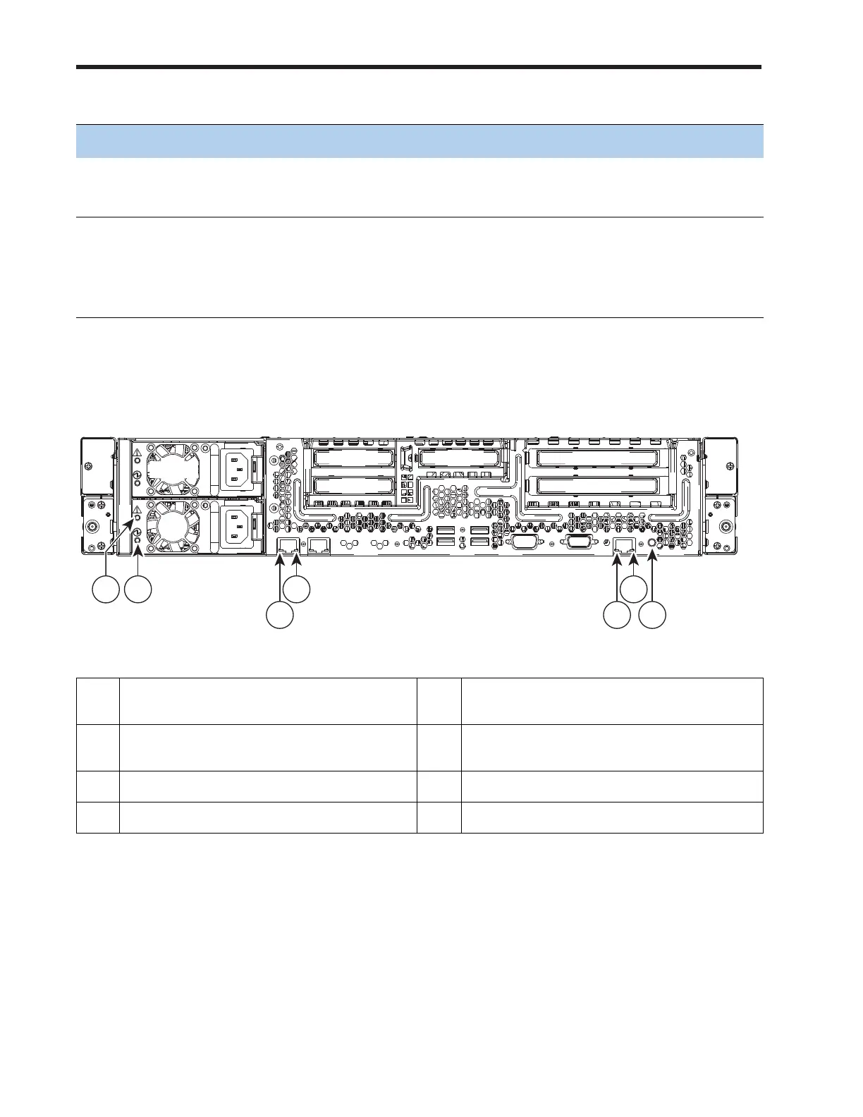
Figure 12 shows the rear panel LEDs.
Figure 12 Rear Panel LEDs
Unit ID
(LED is integrated into
unit ID button)
Off Unit ID not active
On (blue) Unit ID is activated
Power
(LED is integrated into
power button)
Off Server power is off
On (amber) Server power is soft off (power is supplied only to the
CIMC and some motherboard functions)
On (green) Card power is on
1 Power supply fault LED 5 10/100/1000 Ethernet dedicated
management link status LED
2 Power supply AC OK LED 6 10/100/1000 Ethernet dedicated
management link speed LED
3 1-GbE link speed LED 7 Identification button/LED
4 1-GbE link status LED - -
Table 26 Front Panel LEDs (continued)
LED LED State Meaning
285244
PSU 2
PCIe 4
PCIe 3 PCIe 1
PCIe 2
PCIe 5
PSU 1
PSU 1PSU 1
1
2
3
4
5
6
7