-CPU number differs depending on the CPU module
location:
• CPU 1 and heatsink (when module is in lower
bay 1)
• CPU 3 and heatsink (when module is in upper
bay 2)
The CPUs in CPU module 1 must be
identical with the CPUs in CPU module
2 (no mixing).
Note
3
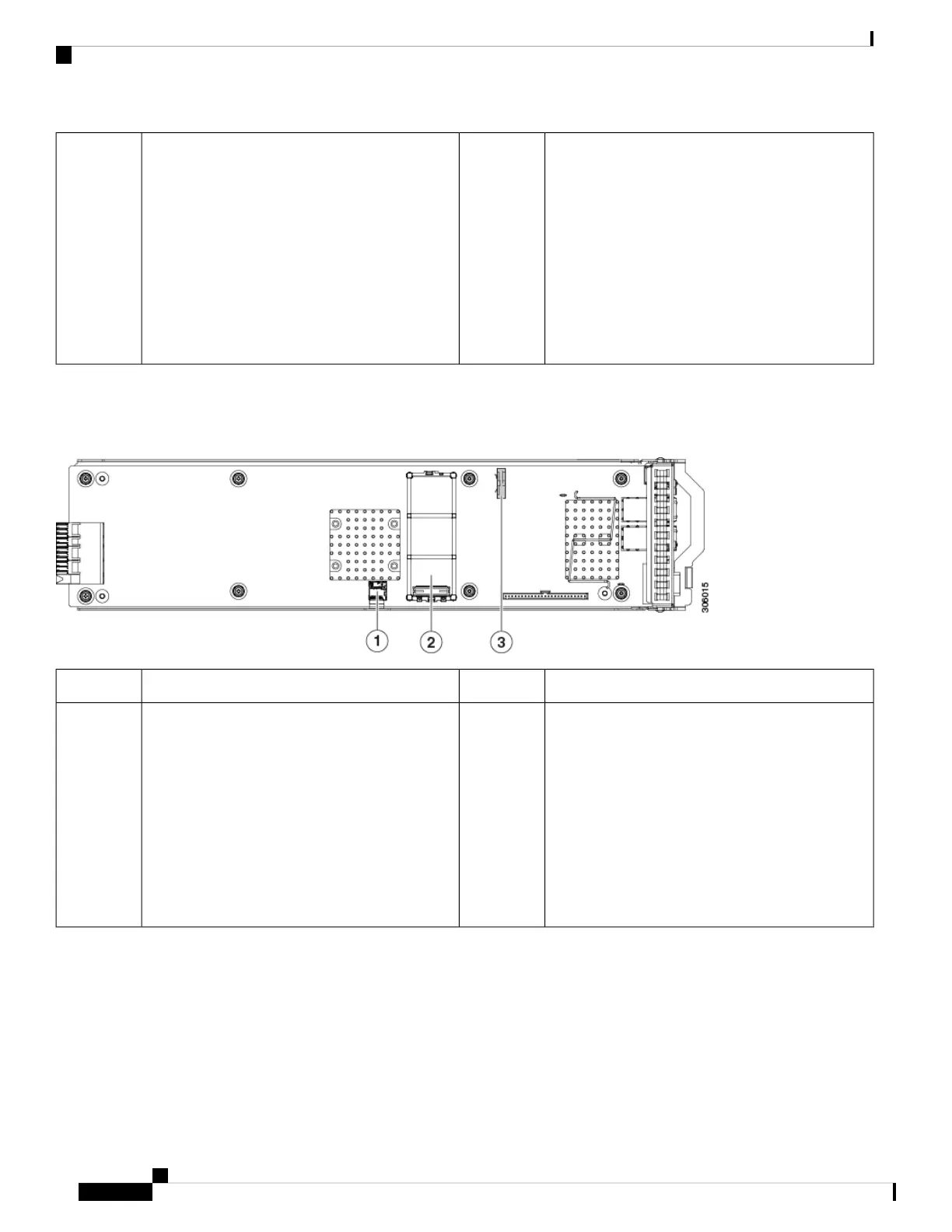
Serviceable Components Inside an I/O Module
Figure 7: Serviceable Component Locations Inside an I/O Module
RTC battery vertical socket3Micro SD card socket1
-Mini-storage module socket. Options:
• SD card module with two SD card slots
• M.2 module with slots for either two SATA
M.2 drives or two NVMe M.2 drives
• Cisco Boot-Optimized M.2 RAID Controller
(module with two slots for SATA M.2 drives,
plus an integrated SATA RAID controller that
can control the two M.2 drives in a RAID 1
array)
2
Maintaining the Server
16
Maintaining the Server
Serviceable Component Locations

 Loading...