• The CPU module has internal fault LEDs for CPUs and DIMMs on the CPU module board. POST and
runtime error detection routines are stored in on-board registers. The contents of the registers are preserved
for a limited time by a supercap voltage source.
To operate the LEDs, press switch SW1 on the board after the CPU module is removed from the chassis.
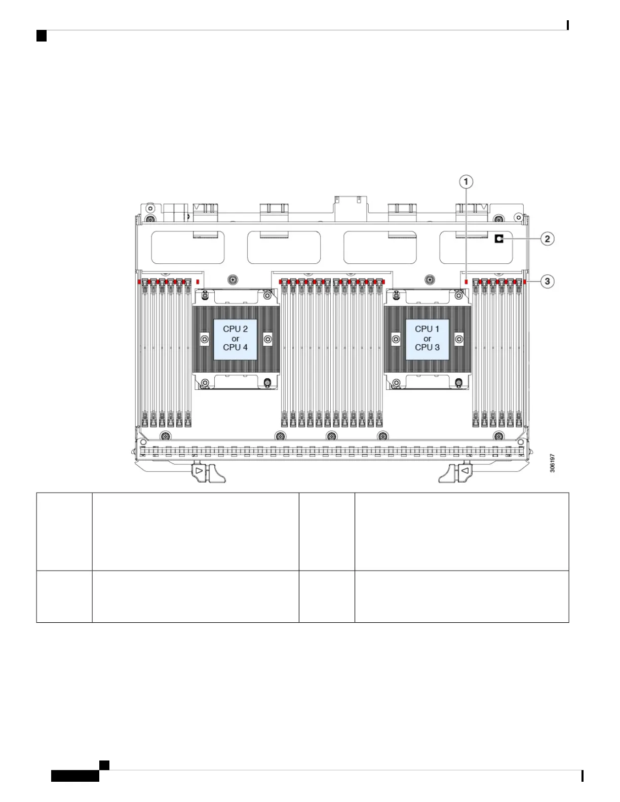
Figure 3: Internal Diagnostic LED Locations
DIMM fault LEDs (one next to each DIMM socket
on the board)
• Amber—DIMM has a fault.
• Off—DIMM is OK.
3CPU fault LEDs (one behind each CPU socket on
the board).
• Amber—CPU has a fault.
• Off—CPU is OK.
1
-Switch SW1
SW1 is labeled, " PRESS HERE TO SEE
FAULTS".
2
Preparing For Component Installation
This section includes information and tasks that help prepare the server for component installation.
Maintaining the Server
6
Maintaining the Server
Preparing For Component Installation
 Loading...