D-2
Catalyst 3560 Switch Hardware Installation Guide
OL-6337-07
Appendix D Configuring the Switch with the CLI-Based Setup Program
Preparing for Setup
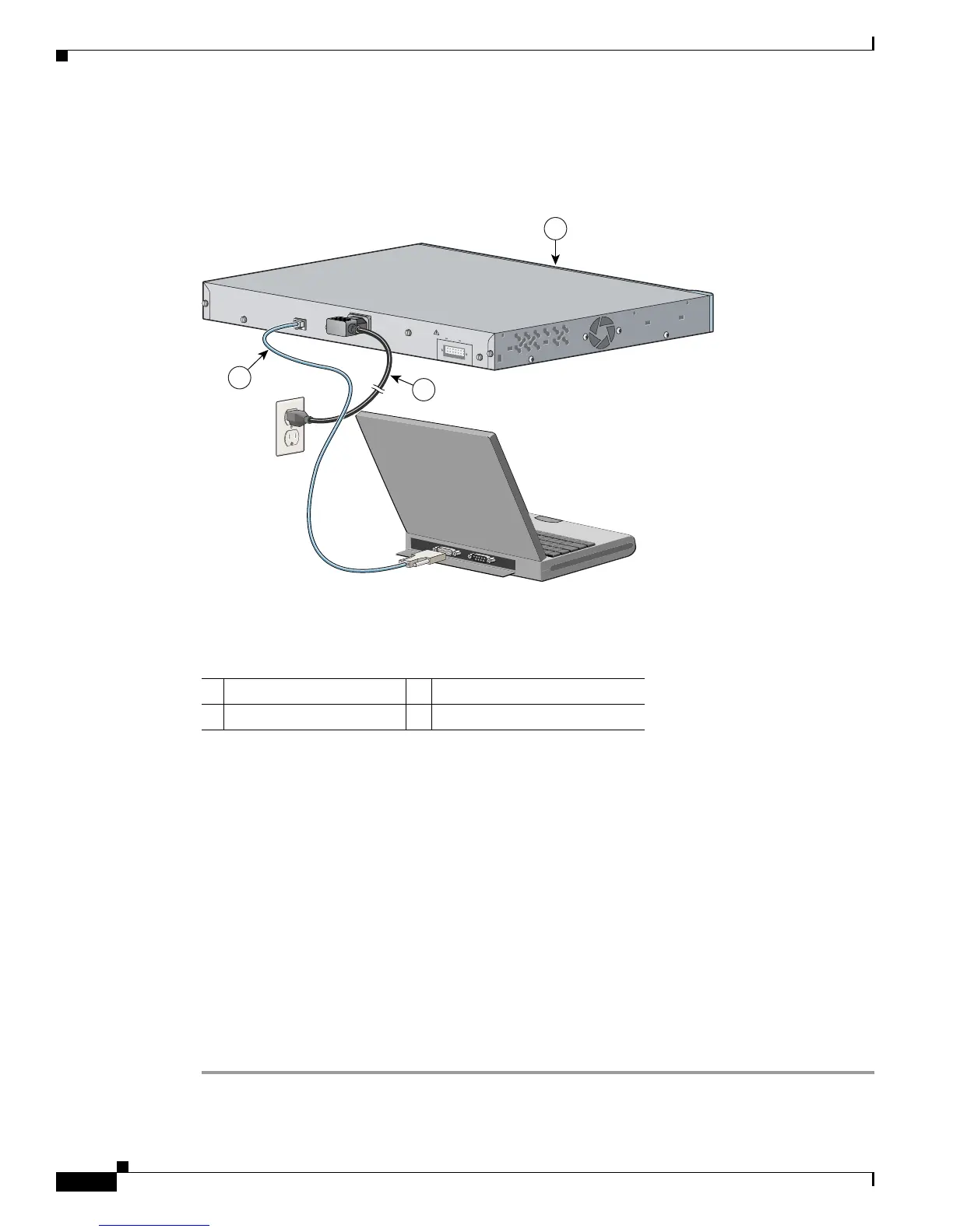
Step 2 Use the supplied RJ-45-to-DB-9 adapter cable to insert the RJ-45 connector into the console port on the
switch rear panel, as shown in Figure D-2.
Figure D-2 Connecting a Switch to a PC
Step 3
Attach the DB-9 female DTE of the adapter cable to a PC serial port, or attach an appropriate adapter to
the terminal.
Step 4 Wait before you power on the switch.
Step 5 Before you power on the switch, start the terminal emulation session to see the output from the power-on
self-test (POST). The terminal-emulation software—frequently a PC application such as Hyperterminal
or ProcommPlus—makes communication between the switch and your PC or terminal possible.
Step 6 Configure the baud rate and character format of the PC or terminal to match these console port default
characteristics:
• 9600 baud
• 8 data bits
• 1 stop bit
• No parity
• None (flow control)
Step 7 Connect one end of the supplied AC power cord to the power connector on a switch rear panel. See
Figure D-2.
Step 8 Connect the other end of the power cable to a grounded AC outlet.
1 Catalyst 3560 switch 3 RJ-45-to-DB-9 adapter cable
2 Power cord
RATING
100-200V ~
5.0A-2.5A, 50-60 HZ
CONSOLE
DC INPUTS FOR REMOTE
POWER SUPPLY
SPECIFIED IN MANUAL
+12v @7.5A -48 @7.8A
2
3
97934
1

 Loading...


